Clearing the Air
By Tim Wheeler, Alkon Corp.
Air-over-oil devices are an economical way to add precise control to simple compressed-air motion. While other technologies have attempted to replace these systems, air-over-oil controls are economical to apply, easy to maintain, and simple to adjust and control. While some associate air-over-oil systems with leaks, oil mist, and aesthetic concerns, there are many ways to safely implement air-over-oil motion control, taking advantage of the savings and simplicity of a well-engineered system.
The Challenges with Pneumatic Motion Control
Since the late 1800s, fluid power has been used to power motion in automation. This use of fluid power remains prominent today, with pneumatic (compressed air) devices powering much of our industry for simple motion tasks. Air cylinders and actuators are among the most prolific devices in manufacturing. They are fast, easy to source, and simple to repair or replace. Additionally, compressed air is clean, easy to generate, and typically readily available on plant floors.
Occasionally, some applications require more control than a simple compressed-air device can provide. Regardless of prior fluid power knowledge, the characteristics of pneumatic applications offer many benefits.
While the rapid, sometimes explosive, expansion of compressed air provides enhanced speed and advantages, the variability in volume and pressure, along with differing forces required for movement, can create challenges.
An easy way to understand the characteristics of compressed air is by imagining a compression spring between force and load. To predict the characteristics of a compressed air system, use the equation:
PV=K. Where Pressure(P) times Volume(V) equals a Constant(K).
For example: Suppose there is a volume of 1 unit of compressed air at a pressure of 100 P*V=100; K=100
Now, suppose a valve is opened connecting another empty 1-unit tank to the existing 1-unit volume, changing the total volume to 2 units:
Using PV=K, where K=100 the pressure will reduce to 50 units to keep the constant (K) at 100.
Likewise, if the volume is reduced to 1/2 units, the pressure will double to maintain the constant of 100. When a valve is opened to release compressed air into an air line to do work, the volume of the system is increased, inducing a pressure drop until the volume is filled and pressure begins to build again. As pressure builds, more force is applied to the actuator and workpiece.
Suppose a pneumatic linear actuator is used to push a wood board through a saw-blade. Again, picture compressed air as a compression spring between the driving force and the wood board.

Table Saw with pneumatic board-pusher.
For this example’s purposes, some variables need to be set:
- The running force required to keep the work-piece moving on the table: 1/2 unit.
- Force required to push the work-piece through the saw blade: 2 units.
- The spring has a spring rate of 1 unit of force/unit of compression.
- The force being applied to the end of the Spring: 3 units. Here’s the effect:
- Begin pushing on the relaxed spring with a 3-unit force.
- The spring begins to compress, but the force is not enough to move the work-piece forward.
- When the spring compresses 0.50 units, creating 1/2 unit of force, the work-piece moves forward.
- When the work-piece contacts the saw-blade, the work-piece stops.
- The spring begins to compress again until it is compressed a total of 2 units, which creates 2 units of force and pushes the work-piece forward, through the saw-blade.
- When the work-piece goes completely through the saw-blade, the running-force requirement drops to 1/2 units, and the spring expands, surging the saw work-piece forward by 1 1/2 units of length.
Far from perfect, this example demonstrates how compressed air can create inconsistent, jerky movement in a motion control system. Encountering variable loads and friction along the path will make it difficult to maintain a smooth movement, and in this example, might result in a poor or inconsistent saw-cut.
Optimizing Compressed Air Motion Control
Converting the board pusher to hydraulic power could be one solution to this issue. Oil is incompressible. While it may be slower in an equivalent-sized system, it provides greater power and control; this results in smoother and more consistent cuts. While converting the drive to hydraulic offers several benefits, there are also downsides. One of the main drawbacks is the cost, particularly in a plant that predominantly uses compressed air.
Another option is to convert the board-pusher to a motor/ball-screw drive. This method may encounter similar cost constraints. Additionally, it adds complexity to an essentially simple, repetitive operation.
On the other hand, compressed air offers all the power needed to operate the saw. By implementing an air-over-oil solution in tandem or parallel, the speed of linear movement is regulated to sufficiently tune out variability created by compressed air. There are three different methods for introducing oil control into a drive system: air-oil tank systems, tandem air-oil devices, and self-contained oil-control units.
Air-Oil Tank Systems
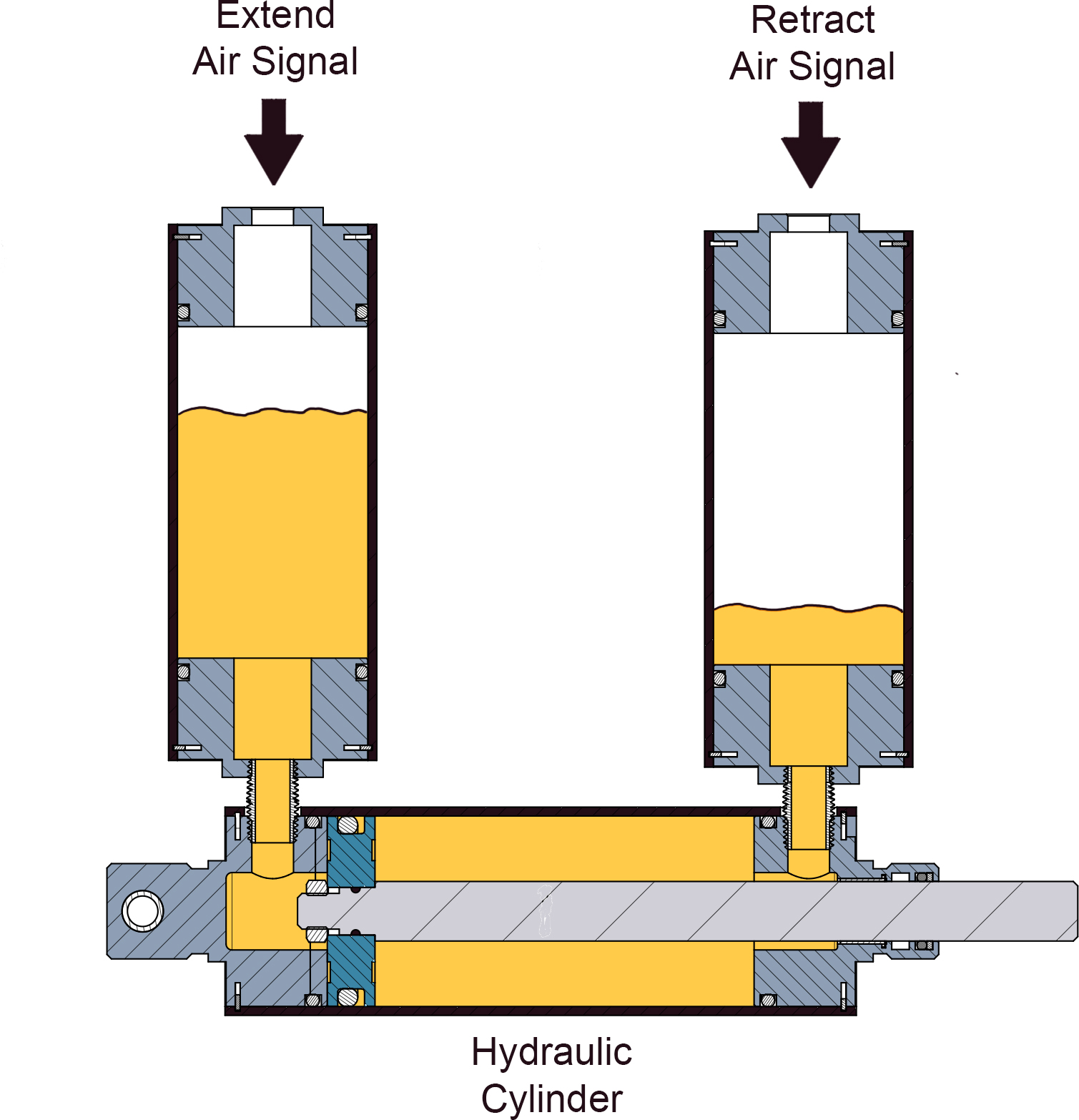
Air-Over-Oil Tank System
An air-over-oil tank system uses compressed air to drive hydraulic oil from two separate tanks into opposite ends of a cylinder through a series of pipes and valves. This creates the force needed to move a load back and forth. This system leverages a standard compressed-air system to provide the necessary force. The compressed air pushes the oil from the tank into the cylinder, extending the piston and moving the load. The incompressibility of oil allows optimal flow rate control.
This transfer of power from pneumatic to hydraulic involves some power loss due to heat, as friction of the lines slightly reduces pressure and movement speed. To enhance these systems, flow controls and check valve options can be built into the lines to allow for rapid advance or free-flowing movement in retract motions.
A major deterrent to using an air-oil tank system is how complex it is to build one. The tank must be sized to accommodate the stroke length. Manually operated leveling valves must be put into place to balance levels occasionally as oil leaks across piston seals during operation. Additionally, each plumbing connection introduces the potential for leaks in the system, which can result in an oily and dirty work site. Depending on the stability and orientation of the tanks, oil-frothing can occur in the system and oil can migrate through its pneumatic portion, resulting in oil-mist being exhausted when the tank is exhausted.
Tandem Air-Oil Devices

Diagram of Tandem Air-Oil Device
An alternative method for achieving air-over-oil performance without investing in an air-oil tank system is to find an actuator that meets the specific force and speed requirements. Tandem air-oil units incorporate a pneumatic cylinder designed synchronously with an oil cylinder that circulates the oil via an attached side-tube from the front to the back of the cylinder. Depending on the design, there may be a reservoir attached to account for oil loss via air-infiltration or oil leakage.
Flow controls and check valve options can be built into the side tubes to allow for rapid advance or free-flowing movement in retract motions. When designing a system from scratch, the increased length of a tandem air-oil device can likely be accommodated. However, modifying an existing system will probably extend the overall footprint. It’s worth noting that these are specialty devices, which may require longer lead times and make obtaining replacement and spare parts more difficult.
Unlike air-oil tank systems, tandem air-over-oil devices share a common shaft that moves in and out of oil and pneumatic chambers within the unit. Even when new, a film of oil will start to wipe-off into the pneumatic chambers and result in an oil mist in the system exhaust. Air can also weep between chambers and cause frothing, resulting in compressible oil. As the unit seals wear, these issues will become more pronounced.
Self-Contained Oil-Control Units
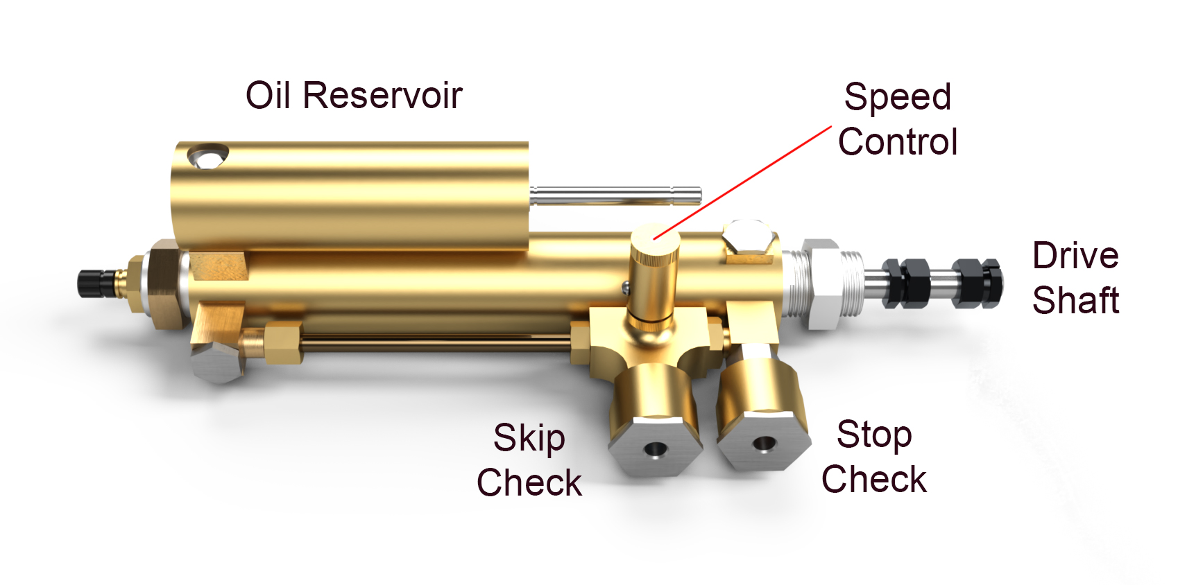
The simplest and cleanest of the options is using a self-contained oil-control unit. These incorporate a standard pneumatic actuator. This maintains the benefits of a pneumatic motion control system and a separate, fully contained oil-control unit. The oil-control unit can be attached mechanically to either the drive system or to the load, allowing the user to adjust speed via flow controls on the oil-control unit. Since oil and pneumatic systems are fully separated, there is no opportunity for frothing or atomized oil exhausting. This combination reaps the benefits of an air-over-oil system while avoiding the pitfalls.
The manufacturing methods for producing the self-contained oil-control units are greatly simplified when compared to the two alternate options. Companies that provide this solution usually have much shorter production lead times while still providing a high level of configurability.
System Options: Versatile, Self-Contained Oil-Control Units
Oil-controlled units are available with options that can adapt the unit to repetitive, familiar operations or with options that offer flexibility and future adaptability.
These include:
- Single Direction Control – Allows free flow in the opposite direction.
- Dual Direction Control – Provides adjustable controls in both directions.
- Dual Speed Control – Allows for different control levels at different points in the travel.
- Skip Check – Gives rapid advance between control regions.
- Stop Check – Complete stop in travel, such as an E-Stop.
Methods of Connecting Oil-Control Devices
Mechanical connections to a cylinder or mechanism need to be robust and secure.
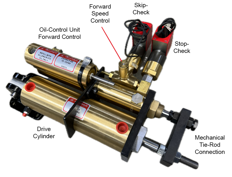
Parallel connection through cylinder rod.
Parallel connections can be made between the shafts of the oil-control unit and the cylinder rod. Cylinders may need to be ordered with an additional rod extension and thread to allow a tie-bar behind a traditional clevis. These units are available for tandem mounting to a cylinder, or parallel mounting tied directly to the work-load.
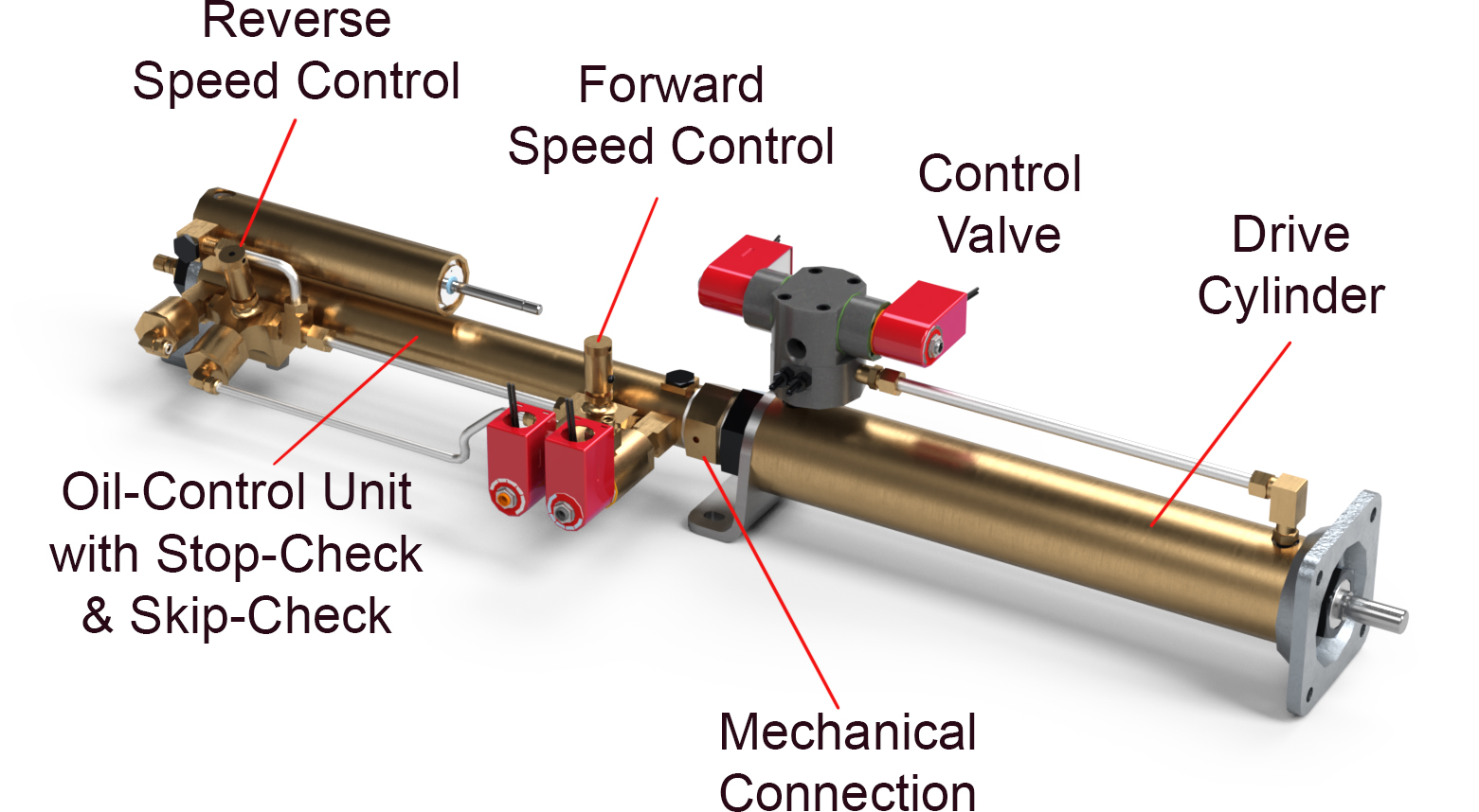
Tandem mounted Cylinder
Work-load Attachments
Conclusion
Oil-control units simplify the implementation of smooth motion control designs through the self-contained, modular nature of the product. They are an ideal way to use engineered products to control and improve new, innovative process operations while minimizing traditional issues stemming from implementing air-over-oil motion controls.

