How to Correctly Interpret Case Drain Flows in Hydrostatic Transmissions
When a pump or motor is worn or damaged, internal leakage increases and therefore the flow available to do useful work decreases. This means that the condition of a pump or motor can be determined by measuring the flow from its case-drain line (internal leakage) and expressing it as a percentage of its theoretical flow. However, using case drain flows to determine the condition of a hydrostatic transmission, without a thorough understanding of closed circuits, can lead to incorrect conclusions and the costly change-out of serviceable components.
Hydrostatic Transmission Basics
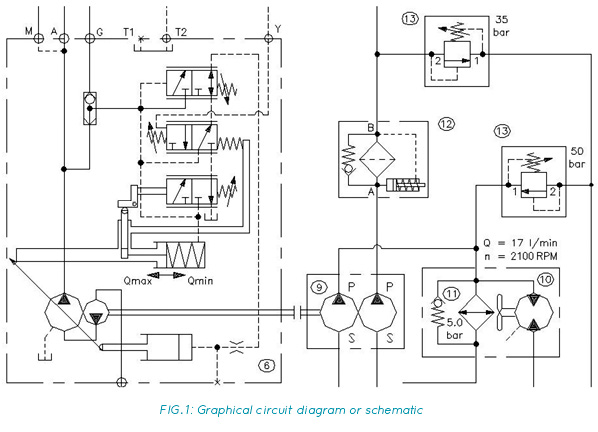
A hydrostatic transmission usually comprises a variable-displacement pump and a fixed or variable displacement motor, operating together in a closed circuit. In a closed circuit, fluid from the motor outlet flows directly to the pump inlet, without returning to the tank (Fig. 1).
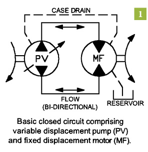 As well as being variable, the output of the transmission pump can be reversed, so that both the direction and speed of motor rotation are controlled from within the pump. This eliminates the need for directional and flow control valves in the circuit.
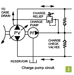
Because the pump and motor leak internally, which allows fluid to escape from the transmission “loop” and drain back to tank, a fixed-displacement pump called a charge pump is used to ensure that the loop remains full of fluid during normal operation.
In practice, the charge pump not only keeps the loop full of fluid; it pressurizes it to between 110 and 360 psi, depending on the transmission manufacturer. A simple charge pressure circuit comprises the charge pump, a relief valve, and two check valves, through which the charge pump can replenish the transmission loop (Fig. 2). Once the loop is charged to the pressure setting of the charge relief valve, flow from the charge pump passes over the relief valve, through the case of the pump or motor or both, and back to tank.
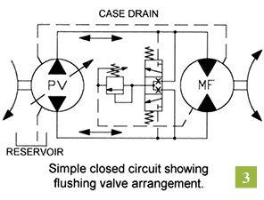
A variation to this charge circuit arrangement is where the transmission is fitted with a purge valve (also called a transmission valve or replenishing valve or flushing valve). Because the fluid in a closed circuit flows directly from the motor outlet to the pump inlet, it means that apart from losses through internal leakage, the same fluid circulates continuously between pump and motor. If the transmission is heavily loaded, the fluid circulating in the transmission loop can overheat. The function of the purge valve is to positively exchange the fluid in the loop with that in the reservoir.
 A closed-circuit purge valve usually comprises a pilot-operated directional valve and a low-pressure relief valve (Fig. 3). When the transmission is in neutral, the directional valve is centered and the gallery to the low-pressure relief valve is blocked. In this state, the purge valve has no function and the charge relief valve in the transmission pump (Fig. 2) regulates charge pressure. When the transmission is operated in forward or reverse, the high-pressure side of the loop pilots the directional valve. This opens the low-pressure side of the loop to the purge relief valve gallery. This purge relief valve is usually set around 30 psi lower than the charge relief valve, and therefore it regulates charge pressure when the transmission is operating in forward or reverse.
A purge valve is most effective when it is located at the motor, assuming the charge check valves (Fig. 2) are located in the transmission pump, as is the norm. The effect of this is that cool fluid drawn from the reservoir by the charge pump charges the low-pressure side of the loop through the check valve located close to the transmission pump inlet. The volume of hot fluid leaving the motor outlet that is not required to maintain charge pressure in the low pressure side of the loop vents across the purge valve relief into the case of the motor and back to tank—sometimes via the transmission pump case.
Drain-Line Gymnastics
This arrangement is important to keep in mind when using case drain flow to determine the condition of a hydrostatic transmission because charge pump flow must be taken into account. Consider an example where charge pump flow is 10 gpm, of which 4 gpm is leaking out of the loop through the motor’s internals (case drain) and 2 gpm is leaking out of the loop through the pump’s internals. The balance of 4 gpm must therefore be going over either the charge or purge relief valve—but still ends up in the pump or motor case, depending on the location of these valves.
 Before any meaningful conclusions can be drawn, the case into which the charge or purge valve relief is dumping (motor or pump) must be determined, and if connected, the two case drain lines (motor and pump) must be isolated from each other. If the charge or purge valve relief vents into the case of the pump, then it is possible to determine the condition of the motor by measuring its case drain flow, but not the pump. If the charge or purge valve relief vents into the case of the motor, then it is possible to determine the condition of the pump by measuring its case drain flow, but not the motor.
In other words, it is not possible to determine the condition of the component that has the charge or purge relief valve dumping into it because there is no way of telling what proportion of the total case drain flow is due to internal leakage—unless the relief valve can be vented externally while the test is conducted.
When conducting these tests, it is also important to understand that the volume of internal leakage from a hydrostatic transmission cannot exceed the flow rate of its charge pump. Consider for a moment, a transmission that has a volumetric efficiency of 100%, that is, the pump and motor have no internal leakage. The transmission loop has a total volume of two gallons and is full of fluid. Because there is no internal leakage, there is no need for a charge pump.
When the pump is stroked to maximum displacement, this circulates the two gallons of fluid in the loop at a rate of, let’s say, 50 gpm. Because it’s a closed loop, with no leakage, the flow from pump to motor is 50 gpm and the flow from motor to pump is 50 gpm.
Now let’s introduce internal leakage of 0.5 gpm in each of the pump and motor. The result is that, with no charge pump, after one minute there will only be one gallon of fluid left in the loop (the other gallon will have leaked back to tank). However, within a second of the transmission starting to leak, the transmission pump will start to cavitate and the severity of this cavitation will increase with each passing second until the transmission destroys itself.
If a charge pump with a flow rate of 1 gpm is installed in the circuit, the problem is solved, temporarily at least. With 1 gpm leaking out of the loop and 1 gpm being replenished by the charge pump, the status quo is maintained—until wear causes the internal leakage of the transmission pump and/or motor to exceed 1 gpm.
As you can see, it’s not possible for the internal leakage of a hydrostatic transmission to exceed the flow rate of its charge pump. Charge pump flow rate is typically 20% of transmission pump flow rate. This means that volumetric efficiency can drop to 80% before the transmission will start to cavitate and ultimately destroy itself. The trick is to overhaul the transmission before this point is reached!
About the Author: Brendan Casey is the founder of HydraulicSupermarket.com and the author of Insider Secrets to Hydraulics, Preventing Hydraulic Failures, Hydraulics Made Easy and Advanced Hydraulic Control. A fluid power specialist with an MBA, he has more than 20 years experience in the design, maintenance and repair of mobile and industrial hydraulic equipment. Visit his website: www.HydraulicSupermarket.com.
Share this information.
Related Posts


Sponsor

Sponsors