A Cost-Effective Alternative: Multiple-Position Pneumatic Linear Slides
By Carey Webster, Engineered Solutions Manager, CFPPS, PHD, Inc.
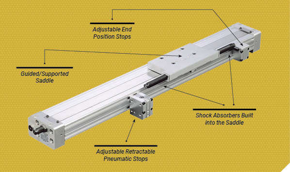
Pneumatic linear slides are used in a wide range of applications throughout many industries. Guided and supported linear motion is the foundation for many of these applications. Over the years, the requirement for flexibility and more productive devices has led to the need for multiple-position linear slides, but providing multiple positions with a pneumatic linear slide can be a tricky proposition.
There have been numerous products introduced using pneumatic servo technology with some success. The compressibility of air, potential contamination issues, and high cost have limited the success of these pneumatic servo systems.
Another more popular alternative is to use electrically driven linear slides using a belt or ball screw drive and servo or stepper motors. This technology has been widely adopted, but comes with a higher initial investment than a pneumatic linear slide. One cost-effective alternative is a pneumatic linear slide using adjustable built-in pneumatic stops to achieve very accurate multiple positions.
The idea of incorporating built-in adjustable stops on a pneumatic linear slide does not fit every application, but is effective where 3 to 5 adjustable positions are needed. The example presented in this article is a saddle or carriage-type pneumatic slide using a built-in rodless cylinder as the drive mechanism. The load-carrying carriage is supported and guided by a built-in precision rail bearing assembly.
The adjustable stops attach to the slide and are locked in place via hardware that engage tee slots in the body of the linear slide. The stops are retractable and are pneumatically extended to stop the saddle whenever the position is required in the application. Retraction of the pneumatic stop allows the linear slide to move to the next required position. Multiple stops can be installed on the saddle slide depending on the number of positions required. Built-in hydraulic shock absorbers in the saddle are used to help decelerate the saddle at each mid-stop. Adjustable end position blocks can be used to shorten the overall stroke if required.
Consideration must be taken for load and velocity used with this type of linear slide. It is advisable to review all application information provided by the manufacturer of any pneumatic linear slide. The attitude (horizontal or vertical) of the slide is an important factor of the application. When linear slides are used in a vertical attitude, the effect of gravity on the load must be considered. Many manufacturers have sizing software available to confirm that the linear slide will perform in each specific application.
One advantage of this type of multiple-position pneumatic linear slide is the positional accuracy provided. Because this uses a positive pneumatically powered mechanical stop, the accuracy and repeatability is much better than that of a slide using pneumatic servo technology. Typically, the repeatability is 0.0016-inch of the original position.
Switches can be used to provide an input signal to various types of programmable controllers or logic systems to indicate the linear slide is in each position. These can be propriety switches designed to fit into the linear slide body or commercially available proximity switches.
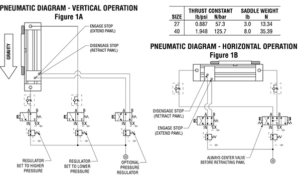
Valving is an important consideration when applying a multi-position linear slide. This type of unit not only requires a directional control valve for the linear slide, but also requires a directional control valve for each intermediate stop. The type of valve used and the manner in which each valve is plumbed is critical to the function of the linear slide.
The multi-position linear slide needs to be controlled by center pressurized (pressure center) or equivalent-type valves. Failure to maintain pressure on both ports of the linear slide when releasing the stopped saddle assembly can cause it to rapidly accelerate upon release of the pneumatic stop. This rapid acceleration can cause physical injury to personnel and/or damage to equipment.
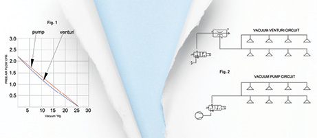
Most linear slides use back-pressure on the exhaust side of the slide piston to regulate saddle speed. Presence of adequate back-pressure is critical when the saddle, stopped by the pneumatic stop actuator, is released. If air opposite of the pressurized side of the slide piston is exhausted to ambient pressure before the saddle is released, the saddle can rapidly accelerate to high velocity before enough back-pressure can build to regulate saddle speed. See pneumatic circuit diagrams in Figures 1A and 1B for the best method of plumbing a multi-position linear slide.
The concept of using a pneumatic linear slide with pneumatic stop actuators provides a simple alternative to electrically driven slides or pneumatic servo slides. The use of hydraulic shock absorbers in the saddle provides deceleration capabilities at each position.
The greatest limitation is the practical number of positions. This concept works extremely well, but there is the ‘law of diminishing returns’ as a user adds more and more mid-positions. The application makes sense with 3 to 5 total positions. More positions may be added depending on the total travel of the linear slide. The designer must consider the additional complexity regarding the number of directional control valves required and the costs associated with those valves and plumbing for each position.
A pneumatic multi-position linear slide using pneumatic stops is a great solution and provides the designer with cost-effective alternatives to traditional types of linear slides.
Related Posts
Get Our Enews!
Sign up for the FPJ Insider Guide
Sign up to receive fluid power industry news, economic updates, professional development content, and product news delivered right to your inbox.
We will never share your data with a third party without your permission. Adjust your email preferences at any time, and unsubscribing is quick and easy.
Fluid Power Journal Resources

