Count on It: Run-Time Monitor Racks Up the Miles
From Webtec
Not too many years ago, the only status indicators in automobiles were a coolant temperature gauge, a voltage or battery charge indicator, a speedometer, and an oil-pressure gauge. Today we can also monitor engine speed and diagnostics, brake pad condition, tire pressure, fuel consumption, air-bag condition, seat-belt usage, windshield-washer level, the progress toward a destination, among other parameters.
But some components remain difficult or impractical to monitor, such as the state of the camshaft drive belt or the condition of the brake fluid. In these cases, the component is usually “lifed,” that is, recommended for service or replacement based on the amount of time it’s been in use or the mileage as measured by the vehicle’s odometer.
A similar situation exists with hydraulic systems. In the past, a hydraulic power unit’s instrumentation was a fluid thermometer, a sight glass, and a pressure gauge. If the system was relatively new, the pressure gauge may have worked, but often its needle would sit at the bottom
of the dial, the victim of pressure spikes or
mechanical vibration.
Today we can reliably monitor not only system pressure and pressure transients but also the flow rate, temperature, cleanliness, and water content of the fluid, plus component vibration and efficiency. As industrial and mobile machinery has become increasingly sophisticated, such predictive maintenance components are more readily available and cost effective as well as necessary. An excavator standing idle due to a burst hose or an unforeseen pump failure on an injection molding machine could be costing thousands of dollars per hour in lost production alone. Unexpected component failures are costly, potentially dangerous, and can pollute the environment.
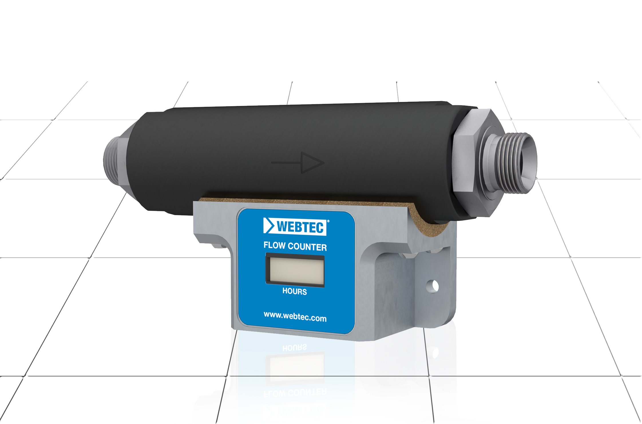
But some hydraulic components are difficult to monitor effectively. Flexible hose condition is one example. Although at least one manufacturer’s product can now monitor hose condition, it is still far from available for all hose applications. As a result, manufacturers recommend changing hydraulic hoses, filters, air breathers, dynamic cylinder seals, and other parts after specified periods of time or usage. Although the passage of time is easily established, machine usage is not always easily monitored. For a process machine operating continuously for two or three shifts a day, usage can be predicted reasonably accurately. But that’s not the case with a piece of farm or construction machinery that is used intermittently or seasonally. In other words, in most cases, hydraulic systems still lack the equivalent of a vehicle’s odometer. Webtec’s RFS200 run-time monitor remedies that situation.
The unit’s principle of operation is a variable orifice flow meter and a magnetic switch that senses the position of a piston. Sensing flow rather than pressure means that trapped pressure or pressure created by reactive loads (or thermal expansion) when the system is shut down cannot generate a false usage reading. The unit can be installed in any part of the hydraulic system and can operate with pressures up to 6,000 psi (420 bar). Flow rates up to 52 gpm (200 lpm) can pass through the unit with minimal flow resistance. For example, with a forward flow rate of 52 gpm (200 lpm) the pressure drop through the unit is typically less than 45 psi (3 bar). It is also possible to direct reverse flow through the unit, although counting does not occur in the reverse flow direction.
The unit is suitable for hydraulic mineral oil to ISO 11158 category HM, with an operating fluid temperature range from -4°F to 212°F (-20°C to 100°C). Timer accuracy is ±0.2% over the specified temperature range. Different port connection sizes and thread forms are available to match with customer requirements. The unit should be mounted horizontally and not installed immediately adjacent to components generating high magnetic fields, such as an electric motor. It should be protected by at least a 40-micron filter in the hydraulic circuit, and oil cleanliness should be maintained better than NAS 8 or ISO 19/17/14. There are two M6 holes for bulkhead mounting, but they should not be used to support pipework. Flexible hoses connected to the unit should be clamped to minimize flexing stress at the threaded ports. Needless to say, all connections should be made by suitably trained personnel.
The unit is preset so that counting initiates when flow through the unit exceeds 2.6 gpm (10 lpm).
This trigger point is unaffected by pressure but may vary slightly with fluid viscosity; higher viscosities decrease the switching flow, and lower viscosities increase it. On reaching the trigger point, a blinking decimal point on the LCD display indicates that the counter is operational, and counting accumulates while the flow rate remains above the trigger point. Being battery operated (with sensitive components protected to IP66), the unit requires no external power supply, and battery life is at least 10 years. There’s no reset function on the unit, so it is effectively tamper-proof, although the unit could obviously be replaced if someone was determined to falsify run-time data. The data output is a visual readout, but options such as an IoT cellular connection for remote data acquisition could be added.
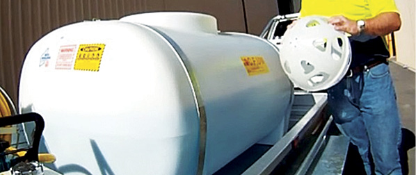
Initially the product was market driven following a request from a customer manufacturing hydraulic attachments in the agricultural sector. Many such attachments are shared by co-operatives, so a foolproof way of charging customers by usage was required. Another customer in the construction-machine business needed to monitor usage for each attachment to determine an appropriate maintenance schedule. Attachments can be changed up to 30 times a day, and keeping track of their usage any other way would be very difficult.
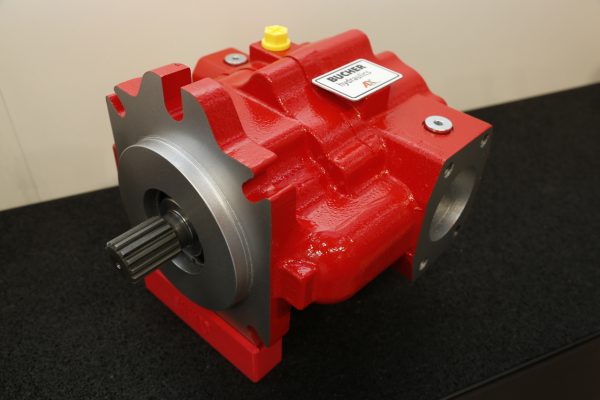
In the industrial sector, applications requiring high flow rates of fluid often use multiple pump systems in which individual pumps are brought online at the appropriate time in the machine’s flow cycle. In some cases, additional pumps may be reserved as standby units used only in the event of the failure of a normal-duty pump. Such arrangements are common in process industries such as steelworks, where a malfunction of the hydraulic system would cause major problems. Keeping track of each pump’s usage would be a significant benefit in planning a scheduled maintenance program for pump overhaul or replacement. The information could also be used to even out the run time of all the pumps in a system, although one school of thought says this is not always the correct approach, since all pumps then approach the end of their useful life at approximately the same time. But by having the relevant usage data for each pump, the maintenance engineer can at least make the most appropriate decision about how the pumps are used.
For fixed-displacement pump systems using unloading valves, the unit could be installed on the system side of the unloading valve to record only the time that the pump is delivering flow at full pressure, rather than the unloaded periods when minimal wear is likely to take place. Alternatively, the unit could be installed on the pump side of the unloading valve, in which case it would record the total pump run time both on and off load. A maintenance engineer or end customer can make the choice.
The condition of hydraulic motors is not always easy to establish using onboard diagnostic sensors, so in applications where they operate for long periods, (such as mixer, shredder, or conveyor drives) the customer can establish a usage-based replacement or overhaul schedule using data provided by a run-time monitor. Component test rigs may also be an application in which the unit may prove useful. Endurance testing often involves operating or cycling components for hundreds or thousands of hours, so the unit’s capabilities to accurately record up to almost 10 million hours of operation cover most requirements.
Share this information.
Related Posts

Sponsor

Sponsors