Energy Challenge: The Hydraulic Solution
Now you will have to endure listening to me explain how I would achieve the most efficient hydraulic system. I gave my solution to the pneumatic challenge in the previous article.
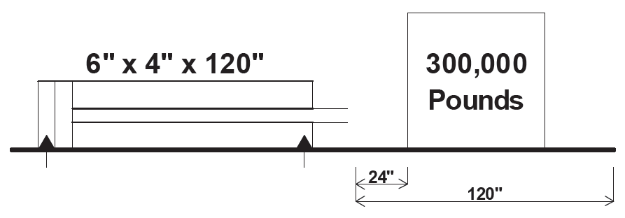
A quick recap for those who may be new to the Journal: A 300,000-pound load has to be moved 8 feet horizontally in 10 seconds by a 6″x 4″ x 120″ cylinder. The load is positioned 2 feet away from the retracted cylinder. The cylinder rod must extend 24″ in one second before it contacts the load and then slide the load sideways covering the remaining 96″ in 8 seconds. The cylinder then immediately retracts fully in ten seconds. We were given a coefficient of friction of 0.25, a tank line pressure of 100 psig, and an assumed system efficiency of 85%. There is a dwell time of 2 minutes before the system repeats. The system operates 12 hours per day and for 6 days per week.
In a subsequent article, I gave you some calculations including the frictional load, the acceleration load, the maximum flow rate, and the maximum pressure. We looked at this information and showed that it would take 292 kW, 202 gpm at 2816 psi to do the job.
But then I had you look at the average power consumption over the 140 seconds of cycle time. We took one-second snapshots of the power usage, and I gave you the average power consumption of 8.84 kW. All you had to do was come up with a circuit that would approach that number. And remember, the goal is to find the most energy-efficient system, not the simplest or the cheapest.
Now, get out your calculator and let’s do some math!
I hope that most of you have immediately concluded that, because of the relatively long dwell time, this system cries out for some type of accumulator. By finding the average flow over the entire cycle time, we might be able to have a constant power draw storing the energy in an accumulator during the dwell time. So, who wants to tell us how to find the average flow rate? I want someone who has not participated before. How about one of you mobile guys? Ok, you with the John Deere cap, what do we do? Right! We take the total cylinder volume, both extending and retracting, and divide it by the cycle time. And what did you find? A total volume of 22.85 gallons divided by a cycle time of 140 seconds (2.33 minutes) gives an average flow rate of 9.81 gpm. So, if we take our average flow and charge a very large or a properly weighted accumulator at 2816 psi, we will need [(9.81 x 2,816) / 1714]/ 0.85 or 18.96 hp, which is 14.14 kW. This is certainly a lot better than the 292 kW, but I think we can do better.
I am going to suggest three things that will dramatically reduce the kW requirements of the system. First of all, I will use a regenerative system for the first two seconds as the cylinder rod moves toward the load. This reduces the average pump flow from 9.81 gpm down to 9.10 gpm. It also makes the extending no-load pressure very close to the retracting pressure. I calculate this knowing a tank pressure of 100 psi will cause a resistive load requiring 125 psi in regeneration and 180 psi in retraction. This makes it practical to think of this as a two pressure system: one for no-load and one for full load. If we try to store all the fluid in a single accumulator, more than half of the volume will be at a pressure that is higher than what is needed. This extra pressure will have to be reduced as pressure drop across a flow control and will waste energy.
So, the second thing I will do is make it a two accumulator system: one for low pressure and one for high pressure. Now, if I choose to use a single pump to supply both pressures, I will waste energy because the pump will spend about half the time at low pressure, which will not keep the motor running near its capacity. (See the article on Power Factor.)
This brings us to the third feature. I will use a double pump, one side with a flow of 4.06 gpm feeding the low-pressure accumulator at 180 psi, and the other side at 5.04 gpm feeding the high-pressure accumulator at 2816 psi.
The kW requirements for this system will be [(4.06 x 180 / 1714) x 0.7457] + [(5.04 x 2816 / 1714) x 0.7457] for a total of 6.49 kW. When we divide this by the given efficiency of 85%, we get 7.64 kW.
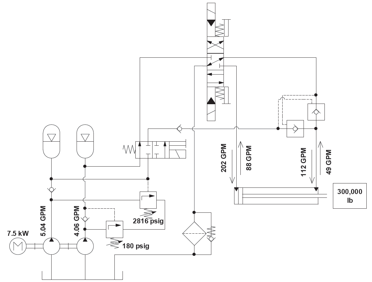
This is how it works: Start the 7.5 kW motor, and the pumps will charge their respective accumulators to the setting of the unloading valves. Once the pressures are reached, the directional valve is shifted to extend the cylinder at low pressure. The pilot-operated check valves in the circuit cause the cylinder to extend in a regenerative mode. After 24 inches of travel, the directional valve is de-energized and the selector valve is shifted directing high pressure fluid to the cylinder. Fluid is returned through the directional valve. When the cylinder reaches the end of the stroke, the selector valve is de-energized and the directional valve is shifted to direct low-pressure fluid to the rod end of the cylinder causing it to retract. Once retracted, the directional valve is de-energized, and the pumps proceed to replenish the accumulators.
The winner is…well, the winner is all of us who have begun to think more about the way we use energy in our fluid power systems.
Share this information.
Related Posts
Sponsor

Sponsors