System Integrators Challenge: The Pneumatic Solution
You may not believe this, but I did not have the solution to the challenges when I wrote the article. I simply chose two scenarios where I knew there would be a variety of pressure and flow requirements that are usually the areas where we tend to lose sight of the energy consumption. As of this printing, I do not know what solutions are being offered, but I am now going to let you know what I think is the best energy solution for the pneumatic portion of the challenge. So get out your calculator and bear with me as we walk through the process.
A quick recap for those of you who may be new to the Journal: A 4″ bore cylinder with a 1″ rod and a 24″ stroke is used to extract a spacer that is wedged between two components. Breaking the spacer loose for the first 1″ of travel requires 1000 pounds of force, but sliding the wedge out of the way only requires overcoming the inertia and the friction factor of 0.15 for the 85-pound wedge and must be accomplished in 1 second. The system rests for 30 seconds and then the cylinder fully extends in 1 second with only the inertia and friction resistance to the end of the stroke. The components are then positioned against the spacer again requiring the 1000 pounds of force to retract. After 10 seconds, the system repeats. This operation runs 24/7.

The challenge is to see who can come up with the most energy-efficient way to accomplish the task. The criterion is the amount of air used in terms of Standard Cubic Feet (SCF).
We calculated the volumes on both sides of the piston in the last article. The rod side volume is 282.72 in3 and the blind side volume is 301.68 in3. We calculated the breakaway force in retraction as 1211.86 pounds. We did not calculate the required extending force. This force will be the inertia load plus the friction load plus the resistive load from the exhausting air at 5 psig. I see this as 10.56 pounds + 12.75 pounds + 62.83 pounds respectively for a total of 86.14 pounds. This will make the pressure required to extend the cylinder 6.54 psig if we use the area of the piston as our force source.
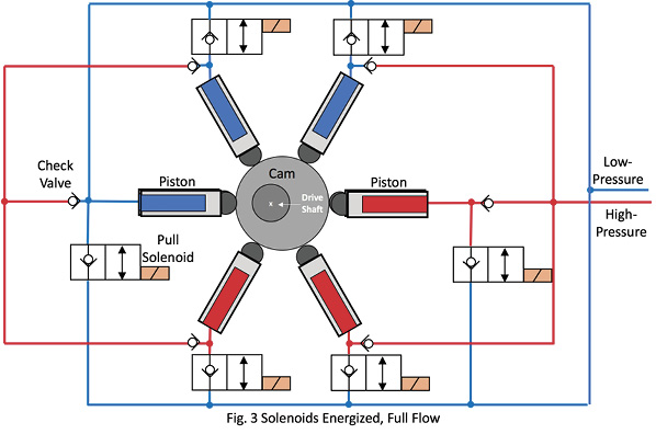
I am going to do two unconventional things in this circuit. First, I am going to use a small accumulator to supply the breakaway force and the volume necessary to fully retract the cylinder. Second, I am going to use a regenerative circuit for the extension of the cylinder. Take a look at the circuit below and then we can do the math.

Energizing solenoid 3 causes the cylinder to extend in a regenerative mode. Energizing solenoids 1 and 2 cause the cylinder to retract.
In order to retract the cylinder, we need to have 1211.86 pounds of force for the first inch of travel. This will require 103 psig. After that, we only need 211.86 pounds of force to complete the stroke requiring 18 psig. If we supply the 103 psig for the whole stroke, after 1 inch of travel the force will produce too much acceleration and the cylinder will bounce as the rapid acceleration overcomes the ability of the exhaust flow to leave the blind end. We could add a meter-in flow control, but that would not reduce the air consumption. Does anyone remember why? Yes, you are right! Once the rod is fully retracted, the pressure will equalize to 103 psi and we will have used the same amount of air that would be required to move the full load the entire stroke. When the cylinder is fully retracted, we should have only 18 psig at the rod end of the cylinder. Any higher pressure will require more air molecules than are necessary.
This is where the accumulator comes in. The volume is determined by doing the math (I know, I know, you don’t want to have to think that hard) to have enough pressure after 1 inch of stroke to complete the breakaway and then have only 18 psig left at the end of the stroke.
I see a hand there in the back. You want to know how to determine the accumulator volume? The rest of you stop smirking. It is a good question. First, we will find the ratio of the final pressure and the initial pressure. The initial pressure is actually 108 psig because we will be consuming some air during that first inch of travel. The ratio then between the initial and final pressures is 3.75:1. The volume of the rod end of the cylinder plus the volume of the accumulator will equal 3.75 times the accumulator volume. The accumulator volume is 103in3. If you have a question about this, we can talk after class or you can send me an e-mail and I will show you my spreadsheet.
Charging the 103 in3 accumulator with 108 psig air, we will provide enough force to breakaway the cylinder and then will provide a constantly decreasing rate of acceleration as the cylinder rod retracts. When the cylinder is fully retracted, there will be only 18 psig in the rod end. If we add a flow control, the result will be the same. The SCF used will be 0.36.
To extend the cylinder, we will use a regenerative circuit. This is not often done in a pneumatic circuit, but it can be a handy tool. To do this, we connect the rod end of the cylinder to the blind end. The effective area is determined by the rod diameter. So we are working on an area of 0.7854 in2. To move the 86.14-pound load, we will need 110 psig. The volume taken up by the rod is 0.7854 x 24 or 18.85 in3. At 110 psig, this translates into about 160 in3 or 0.09 scf.
The total scf per cycle is 0.45 scf. The average flow rate will be 0.66 scfm. This is 346,896 scf/year. If the facility is paying $0.10 kWh, it would be at a cost of $115.63 per year. If we had used the maximum pressure of 110 psig, we would have increased the scf/year to 2,175,038 at a cost of $725.01 per year. We just saved the facility $609.38 per year.
Share this information.
Related Posts

Sponsor

Sponsors