Get a Load of This: Pneumatic Cylinder Sensor Technology
By Jack Moermond, Service Engineer, Balluff Inc.
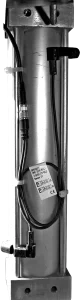
In the field of automation, the pneumatic cylinder is a popular choice for prime mover duties. Pneumatic cylinders carry advantages such as relatively low first cost, application simplicity, and durability. To integrate a pneumatic cylinder into an automated system, it is necessary to supply electrical signals to the controller indicating the position status of the cylinders. Toward that end, pneumatic cylinder manufacturers, machine builders, and end users have developed a number of ways to detect extension or retraction of a pneumatic cylinder and provide an electrical signal to the control system.
 One position-sensing technique is to install external electromechanical limit switches or inductive proximity switches that detect metal flags on the moving parts of the machine. The disadvantages of this approach include the cost and complexity of the brackets and associated hardware, the difficulty of adjustments, and the increased physical size of the overall assembly. Another problem: the external hardware is prone to damage and misalignment from everyday contact.
A more popular and widely used method is to attach magnetically actuated switches or sensors to the sides of the cylinder or into a slot extruded into its body. Through the pneumatic cylinder’s aluminum wall, magnetic field sensors detect an internal magnet mounted on the moving piston. In most applications, magnetic sensors provide end-of-stroke detection in either direction; however, installing multiple sensors along the length of a cylinder detects additional discrete positions.
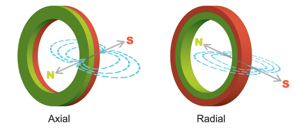
There are two common types of cylinder magnets used with magnetic field sensors. The first and probably most widespread is the axially magnetized magnet, which is ideal for actuating most reed switches. As shown in the side-view illustration to the right, the magnet places the north and south poles next to each other in the axial plane as shown in the illustration.
A second commonly encountered cylinder magnet is a radially magnetized magnet one. It works well with a Hall effect sensor. Instead of the north and south poles next to each other, one is the inner diameter and the other is the outer diameter, as shown in the upper right. The Hall effect sensor only looks for a magnetic pole; it does not matter if it is north or south.
Reed switches
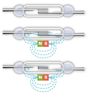
The simplest magnetic field sensor is the reed switch. This device consists of two flattened ferromagnetic nickel-and-iron reed elements enclosed in a hermetically sealed glass tube. The glass tube is evacuated to high vacuum to minimize contact arcing. As an axially aligned magnet approaches, the reed elements attract the magnetic flux lines and draw together by magnetic force, thus completing an electrical circuit. The magnet must have a strong enough Gauss rating, usually in excess of 50 Gauss, to overcome the return force, i.e., spring memory, of the reed elements.
 The benefits of reed switches are that they are low cost, require no standby power, and can function with both AC and DC electrical loads. However, reed switches are relatively slow to operate; they may not respond fast enough for some high-speed applications. Since they are mechanical devices with moving parts, they have a finite number of operating cycles before they eventually fail. Switching high-current electrical loads further cuts into their life expectancy. In addition, low-cost reed switches can sometimes deliver multiple switching points as the twin lobes of certain magnets pass by. Lastly, reed switches installed in high shock and vibration applications may exhibit contact bounce or become physically damaged. In many automated factories, reed switches are a major source of unplanned downtime. In plants with hundreds of reed switches, failures can occur almost hourly. They represent a continuous maintenance headache, not to mention lost productivity.
Hall effect sensors
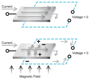
Hall effect sensors are solid-state electronic devices. They consist of a voltage amplifier and a comparator circuit that drives a switching output. In a Hall effect sensor, a steady DC current passes through the thin Hall effect chip. The distribution of electrons across the element is uniform, and the current moves in a straight line with no potential difference generated at the outputs on the sides of the chip. As a radially oriented magnet approaches, the magnetic field is perpendicular to the current flow through the Hall element. The presence of the perpendicular magnet pushes the electrons out of their straight-line path and toward one side of the chip. The imbalance of electron charge thus creates a potential voltage across the Hall effect element. The small microvoltage this creates is proportional to the strength of the magnetic field. Once the voltage amplitude generated across the chip satisfies the threshold level of a comparator circuit, the sensor output switches on.
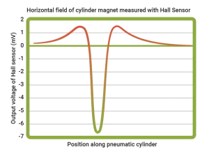
 Since Hall effect sensors are electronic devices, they have no moving parts. Unlike a reed switch, their response time is not dependent on magnetic force overcoming mechanical inertia. They operate faster and are more resistant to shock and vibration. It might seem like an easy solution to simply replace reed switches with Hall effect sensors. The problem is that the magnetic field orientation of a cylinder designed for reed switches may be axial, whereas the orientation for a Hall effect sensor is radial. The result: a chance that a Hall effect sensor won’t operate properly when activated by an axially oriented magnet. Another concern is that Hall effect sensors typically have low sensitivity, such that the magnetic field strength must be 30-60 Gauss. Finally, some inexpensive Hall effect sensors are susceptible to double switching, which occurs because the sensor detects both poles of the magnet, not simply one or the other.
AMR magnetoresistive sensors
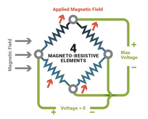
Another type of solid-state magnetic field sensor is the AMR magnetoresistive. Its operating principle is simple: the sensor element undergoes a change in resistance when a magnetic field is present, changing the flow of a bias current running through the sensing element. A comparator circuit detects the change in current and switches the sensor’s output. Compared to Hall effect sensing technology, which generates a tiny microvolt-level signal, the magnetoresistive element responds with a more robust 3-4% change in bias current. This results in more noise immunity and less susceptibility to false tripping. Magnetoresistive sensors are about 200 times more responsive than a typical Hall effect sensor to a given magnetic field strength. The practical magnetic field strength required to operate a magnetoresistive sensor can be as low as 15 Gauss. Improvements in magnetoresistive technology now allow these sensors to detect both axially and radially magnetized magnets.
 In addition to the ruggedness benefits of solid-state construction, the magnetoresistive sensor offers better noise immunity, smaller physical size, and lower mechanical hysteresis (i.e., the difference in switch point when approaching the sensor from opposite directions). Quality manufacturers of magnetoresistive sensors incorporate additional output protection circuits to improve overall electrical robustness, such as overload protection, short-circuit protection, and reverse connection protection. Unlike Hall effect sensors, there are no double-switching points because the higher sensitivity of the magnetoresistive sensor allows it to remain on as the low-strength portion of the magnetic field passes under the sensor. Hall effect sensors, being less sensitive, often drop out at a weaker portion of a magnetic field located between two stronger areas. They switch on again when the field strength increases.
Leading manufacturers of magnetoresistive sensors have developed weld field immune versions that operate reliably in AC welding fields as strong as 200kA/m with no false signals or electrical damage. Many of these welding sensors are available with metallic housings to further guard against hot weld spatter that would melt into a plastic-bodied sensor.
Over the years, many users have abandoned the use of reed switches due to their failure rate and have utilized mechanical or inductive sensors to detect pneumatic cylinder position. AMR sensors are smaller, faster, and easier to integrate. They are much more reliable, but they must overcome a stigma left by their predecessors. With the vast improvements in sensor technology, AMR sensors should now be considered the primary solution for detecting cylinder position.
Share this information.
Related Posts
Norstat Adds Connectors for Fluid Power Applications

Then and Now: Energy Awareness
ISO Standards for Hydraulic Systems and Pneumatic Systems
Tips for Efficient Compressed Air Filtering
Hydraulic Circuits: Industrial Valve, Mobile Valve, or Diverter Valve?

2015 Salary Survey: Looking for Participants
Sponsor

Sponsors