Hold It Right There: Methods for Stopping a Linear Pneumatic Actuator’s Movement in Mid-stroke
By Richard Bullers, SMC, CFPPS
A machine operator defeats a guard and reaches his hand into a machine to reset a part in a nest, but misjudges the speed of the press. Does the pneumatic actuator driving the tooling cause a serious injury or were other steps taken to stop the actuator in time?
As you can imagine, stopping and holding a pneumatic actuator in mid-stroke can be an important design feature. Application examples include positioning a part in more than one location, preventing a machine crash in the event of a fault, or including a redundant safety function in a machine.
If you are unfamiliar with the methods, functional considerations, performance, or safety aspects of stopping and holding a linear pneumatic actuator in mid stroke, this article can serve as a starting point for making the right decisions based upon realistic performance expectations.
Prerequisites
Consider the following questions and answers when selecting a linear pneumatic actuator that must be capable of stopping anywhere along the stroke.
1. What type of linear actuator should I use or avoid?
Selection of the correct actuator is a critical part of the process. The term actuator encompasses many types of pneumatic drives, including single acting cylinders, double acting cylinders, rotary actuators, air chucks or grippers, and air bellows. The focus of this article is on double acting cylinders where air is supplied and controlled to both sides of an internal piston.
Actuators that have inherent leakage due their construction are avoided. Leakage makes it virtually impossible for an actuator to hold a specific position after it has been stopped. Examples include “band cylinders” and vane type rotary actuators.
“Single acting” cylinders incorporate an internal spring for automatically returning or extending them to a home position and are not used for positioning, but may provide an ancillary function such as driving a shot pin into a lock. Avoid them for positioning, but consider them for complementary functions.
A type of double acting actuator that is ideal for stopping in mid-stroke is known as a “locking cylinder”. This type of actuator incorporates an internal mechanical lock to hold the rod in place once cylinder motion has stopped.
2. How much load is appropriate?
An overloaded actuator will be more difficult to control or stop and will also be subject to accelerated wear or failure. Manufacturers use different ways to answer this question, but one method used to quantify load is with a “load ratio”.* Load ratio for purposes of this article is:
LR = (actual force/theoretical force) X 100%
The actual force is the weight of the load, friction, and any other external force the actuator has to overcome. The theoretical force is the force produced by the actuator as pressure pushes against the cross sectional area of the piston and is commonly represented by the formula:
F = P X A where F = force, P = pressure, and A = cross sectional area of the cylinder
For linear actuators use a load ratio of 50% or less. Lower load ratios generally improve stopping performance. For example, a cylinder exerting 500 lb. of force would use a load of 250 lb. for a 50% load ratio. A 150 lb. load on the same cylinder would represent a 30% load ratio.
3. What type of stopping performance can I expect?
Realistic expectations of what can be accomplished with the methods described take into account the following facts:
The compressibility of air prevents stopping an actuator with precision. Expect the cylinder to overrun a stop point and do not expect to be able to repeat a stopping at a specific point each time.
All elastomer seals used in pneumatic components have some level of leakage that will increase with wear. Expect the actuator to “drift” away from the point it stops over time unless a mechanical lock is also used to hold it in place. Do not expect a pneumatic actuator to hold position for extended periods of time by only using the method of trapping pressure with elastomer seals.
Not every factor affecting performance can be anticipated. Sizing of the actuator and components in the pneumatic circuit is theoretical. Actual performance requires validation through testing of the circuit under actual working conditions. Expect the results to vary.
Lower actuator speeds and load ratios will improve stopping performance.
Methods
Use of a Closed Center Directional Control Valve
 Directional control valves send pressure to the port on one side of a double acting cylinder while allowing the opposite side to exhaust to atmosphere. They will have a minimum of two positions for the internal valve spool that will shift from one position to the other to either extend or retract a pneumatic actuator. A 5 port, 2 position valve is abbreviated as a “5/2” valve.
A number of directional control valves will have three positions with the center position providing a specialized function. Springs on each side of the valve spool force it into the center position when no energy is being applied to shift the valve spool.
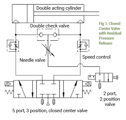
A “closed center” valve blocks pressure at all ports in the center position and will trap it between the valve and actuator. This stops the actuator’s movement. “Rubber seal” valves that have a lower leakage rate are used. Avoid any valve described as “metal seal”.
When a closed center valve is used, a method of safely relieving pressure from between the cylinder and directional control valve is prudent. A method of residual pressure release, such as use of a double check valve, needle valve, and 2 port, 2 position valve (abbr. “2/2”) is used in Fig 1.
Pilot Operated Check Valves
 A check valve only allows flow in one direction. A pilot operated check valve (abbr. “P.O. check”) stops the flow of air in one direction, but if a pilot signal is present, the valve will allow flow in both directions. A P.O. check is sometimes combined with a speed control and designed to connect directly to an actuator port or may be offered as a pair in a stand-alone assembly.
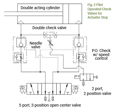
When two P.O. checks are connected directly to an actuator’s ports and use a circuit that exhausts both pilot signals, they will stop an actuator in either direction. For this purpose the lines providing the pilot signals to the P.O. check valves are integrated into a circuit using an “open center” (also called “exhaust center”) valve. An open center valve allows both cylinder ports to exhaust to atmosphere when no energy is being applied to shift the valve spool (Fig 2).
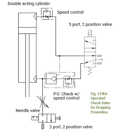
A single P.O. check can be used for “drop prevention” when an actuator is oriented vertically. If air pressure is lost the load will be stopped when the signal to the P.O. check is exhausted (Fig3).
Stop Valves
 A 2/2 valve that allows air flow in both directions is also called a “bi-directional” valve. By using air pilot signals to operate a pair of 2/2 valves connected to the actuator ports the actuator can be stopped when the pilot air is exhausted. This is similar to the type of logic illustrated in Fig. 2, but with the advantage of being able to use other types of directional control valve function than “open center”.
Force Balance
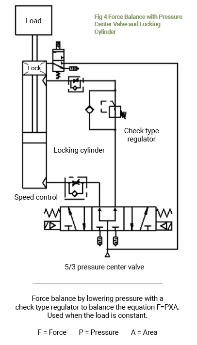
A “pressure center” 5/3 valve is used for a force balance circuit. This type of valve sends pressure to the A and B output ports simultaneously. The flow path in a pressure center valve forms a circuit loop from one side of the piston through the valve and back to the other side of the piston. For this reason an external force can move the piston rod unless an equal force is created on the opposite side of the piston as a counter balance.
A “check type regulator” is used between a 5/3 pressure center valve and the side of the actuator piston that is exerting too much force for counter balance. A check type regulator allows air to flow back through and around the regulator when pressure to the regulator is exhausted. As pressure is reduced, the force is reduced. When the force on each side of the actuator piston is equalized, the actuator will stop.
This type of circuit logic is often used with locking actuators which require the actuator to be fully stopped before a brake is applied to prevent scoring of the piston rod and accelerated wear. A force balance can also be used with standard actuators; however, any change in the load also requires a compensating change in pressure to hold the actuator’s position.
A force balance circuit also ensures that “back pressure” is present when the directional control valve is shifted to continue the extension or retraction of the cylinder. “Back pressure” is the pressure in an exhaust flow path that ensures a smooth and controlled restart of cylinder movement.
If pressure is introduced to one side of the piston while no “back pressure” is on the other side of the piston the cylinder rod and load may “shoot out” with little or no control resulting in a high speed impact at end of stroke. Damage or injury can result from high speed cylinder impacts.
In a “locking cylinder” circuit a 5/3 pressure center valve and check type regulator are used to achieve a force balance while a separate valve is used to operate the lock mechanism. These valves are operated sequentially so the lock mechanism is not being applied during piston movement.
Hard Stops
 The most accurate way to stop a pneumatic actuator in precisely the same location each time is with a hard stop. This can take a number of mechanical forms, including stops that can be moved into and out of position as needed.
A critical factor in using hard stops is determining the amount of kinetic energy generated by the actuator’s terminal velocity and mass being moved and the ability of all components to safely absorb this energy. Use of slower speeds or deceleration technology such as a shock absorber may be required to prevent machine damage or a hazardous situation.
Performance
For better stopping accuracy reduce the volume in the pneumatic circuit by locating the directional control valve as close to the actuator as possible. The use of precision regulators may help with repeatability if trying to stop the actuator in the same location each time.
Consider leakage in the circuit as inevitable and do not rely upon elastomer seals alone to hold an actuator’s position for prolonged periods of time.
Ensure the cylinder is correctly sized for the load and there is sufficient flow capacity for the directional control valves, tubing, and other components. Contact the manufacturer of the components or a certified fluid power pneumatic specialist if you do not have sizing information
When a higher level of stopping accuracy is required, but use of a hard stop is functionally prohibited, consider an alternate technology such as air/hydro systems, hydraulic circuits, or electric actuators
Safety
Never employ a cylinder stopping method without redundancy, (in particular a mechanical lock) when a hazardous situation may result from a component failure in the circuit. It’s no different than crawling under your car. You don’t depend upon the elastomer seal alone in the hydraulic bottle jack (cylinder) but place a jack stand (mechanical lock) to prevent a crushing hazard.
Pressure trapped within the pneumatic circuit is considered a potential safety hazard. The circuit design must account for the controlled release of trapped energy to avoid unintended consequences.
The startup of an actuator after stoppage should account for the safe introduction of pneumatic energy back into the machine to prevent any unplanned motion, shoot out of piston rods, or sequence mistiming that could result in machine damage or a hazard.
Always perform a safety analysis. Use a recognized safe machine design methodology such as ISO standard 13849-1. If unfamiliar with these practices, seek assistance from qualified professionals.
Share this information.
Related Posts

2 thoughts on “Hold It Right There: Methods for Stopping a Linear Pneumatic Actuator’s Movement in Mid-stroke”
Leave a Reply
Sponsor

Sponsors
Very well written. Pneumatic are a tricky business, you need to be very sure about the choices and equipment you are choosing. Relying over a renown and quality famous brand is one thing you can do to cut some tension. Brands like Utah Pneumatic are famous for their quality and services, you can check them through
https://utahpneumatic.com
good morning, major blog on lardy loss. comparable helped.