Hydraulic Cylinder Cushions Fight Mechanical Shock
By Tony Casassa, Application Engineer, Aggressive Hydraulics
Every day, hydraulic cylinders work to push, pull, tilt, raise, and hold loads on diverse equipment. Often the operator is responsible for gradually stopping the cylinder in a controlled manner.
However, in some applications, the cylinder may fully extend or retract and reach the end of the mechanical stroke, but it is not stopped by the operator. This likely is not a problem if the speed is slow. If there is a high-inertia load, when the cylinder reaches the end of stroke the sudden stop can cause mechanical shock, with effects ranging from mild annoyance to serious risk.
Inertia is a product of mass and speed. Consider a hydraulic cylinder pushing or pulling a wheeled cart horizontally. When the cylinder moves slowly and reaches end of stroke, the change of speed is small and does not cause any problems. If the hydraulic flow increases and the cart moves at a higher velocity, the inertia increases, and the resulting potential shock at the end of stroke also increases. Because the cart has wheels and is moving horizontally, increasing the mass of the cart will cause only a small increase in the pressure required to move the cart, but it will cause a larger increase in the inertia.
Now imagine the cylinder moving the cart up an incline. The pressure required to move the load is higher. When the cylinder reaches the end of stroke, the pressure still increases to the system maximum, but the increase is smaller; therefore, the shock is less. On the other hand, if the cylinder moves the cart down an incline, the inertia will increase, and the shock will be higher.
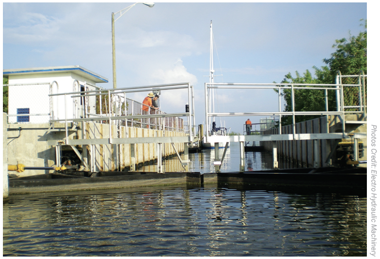
Another example is a hydraulic cylinder opening and closing a swinging gate around a pivot point. Typically, the cylinder is mounted near the pivot point and provides a relatively high force and short stroke. Due to mechanical advantage, every inch of cylinder travel multiplies into a longer distance for the gate’s edge. The wider the gate, the further the edge is from the pivot point, and therefore the higher the rotational inertia of the gate.
A strong shock at the end of cylinder stroke can damage machine components, negatively affect machine performance, or present a risk to the machine operator. When the load moved by a cylinder comes to a sudden stop, stress is applied to the cylinder and the machine’s mechanical structure. Excessive stress on these structural components and pressure spikes in hydraulic tubes or hoses can cause premature failure. Shock can also degrade machine productivity. For example, if a cylinder is moving a load of aggregate material, it may cause some of the material to fall out of the bucket or container. Of highest importance is the potential risk to the operator. For example, the operator in an aerial work platform requires the cylinder to come to a slow, controlled stop.
Historically, the responsibility would be on the operator to slow and stop the cylinder to prevent any undesirable shock. Now there is increasing market demand for user-friendly machines, and industry and safety regulations place more responsibility on the machine designer.
In some cases, the best solution is the addition of switches or sensors to detect cylinder position, a proportional hydraulic valve to control the flow, and a programmable logic controller to read the input and determine the output. However, due to cost, serviceability, or operating environment, the electronic solution may not be suitable.
End-of-stroke cushions
Hydraulic cylinders with end- of-stroke cushion features have been available for many years, with the most familiar being spear-type cushions, which are common in tie rod construction cylinders but also used on welded construction cylinders.
Spear-type cushions. Spear-type cushions can be nonadjustable, but more often they’re adjustable. This type of cushion can be effective, but it also has some shortcomings to consider. Because the design has a spear or sleeve that enters and exits a concentric pocket, if the difference between the spear and pocket diameter is too small, there is a risk of metal-to-metal contact and galling. On the other hand, if the clearance is too large, the effective orifice will be too large, and the cushion will be ineffective.
A downside from the design standpoint is that the cushioned flow has two parallel paths. Oil flows through the annular area created by the spear and pocket as well as across the fixed orifice or adjustable needle valve, resulting in a complex scenario for predicting the flow. The spear-type design requires space in the head and end cap for the cushion-adjusting needle valve and the check valve for incoming flow. Lastly, although the ability to adjust the cushion may have advantages in some circumstances, it also allows the possibility of incorrect adjustment; for example, an operator seeking to improve productivity without understanding the potential negative consequences.
Cushion piston. The cushion piston is an alternate solution to provide the cushion function and offers advantages over the spear-type cushion. This solution can be designed for a wide range of flows and can be more effective in a lower flow range than the spear type. The controlled flow passes through a single orifice, which allows more predictable cushion performance. The orifice and the check valve function are built into the piston, requiring no further space increase than the length of the cushion zone, keeping the cylinder compact in size. It is nonadjustable, which prevents the possibility of malfunctions caused by improper adjustments.
As the name suggests, the features that provide the cushion effect are built into the piston. On the outside diameter of the piston, in addition to the typical bidirectional elastomeric piston seal, a cast-iron piston ring is added in each direction the cushion is desired, either on the blind end for a cushion at full retract, on the rod end for a cushion at full extend, or both as shown in figure 1.
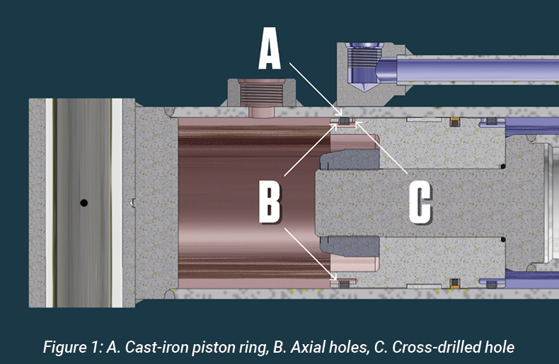
The groove for the cast-iron piston ring is wider than normal, allowing it to shift slightly in the groove. In addition, on each end of the piston there is a series of axial holes and a single cross-drilled hole.
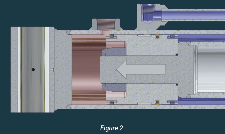
These features do not affect the cylinder operation during most of the stroke. Flow can freely enter and exit the cylinder, and the elastomeric piston seal prevents internal leakage. The cast-iron ring can “float” in the wide groove, and the pressure is the same on both sides of the ring. When the cast-iron ring passes the port, the exiting flow is forced through the axial and cross-drilled holes, creating a pressure drop. With higher pressure on one side, the ring is forced to the opposite side of the groove, and flow must pass through the single cross-drilled hole.
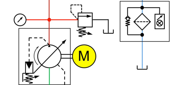
If properly sized, the orifice controls the flow rate of oil exiting the cylinder. The pressure of the incoming fluid increases until it reaches the maximum level, as determined by the setting of a component outside the cylinder, commonly a relief valve or a controller on a variable displacement pump. The relief valve must open to divert the flow that cannot enter the cylinder, or the pump displacement must decrease to reduce the flow (figure 2).
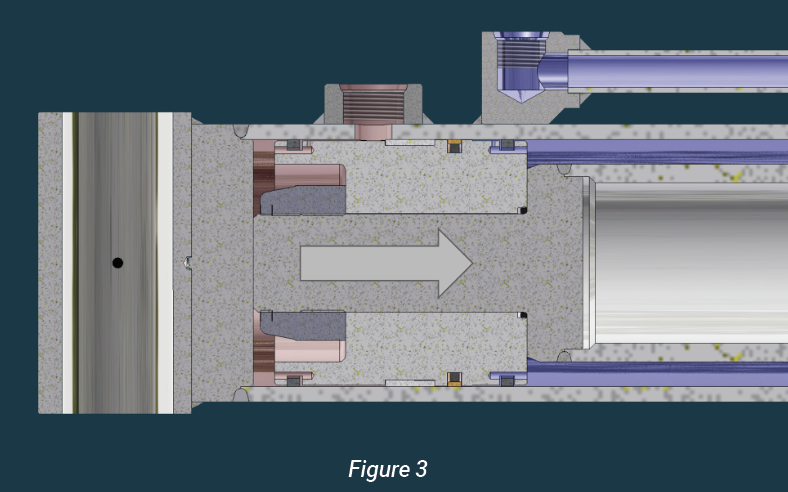
Although the cushion may be desirable to slow the cylinder at the end of stroke, when the direction is reversed it is preferred for it to operate immediately at a normal speed. This is the reason the groove for the cast-iron ring is wider than normal. Just as the pressure drop of the exiting flow moved the cast-iron ring to one side of the groove, now the pressure drop of the entering flow moves it to the opposite side. The flow can now pass under the cast-iron ring and out the axial holes with minimal or no restriction. This feature is referred to as fast start-up. After the cast-iron ring passes the port, fluid flows directly into the cylinder, and once again, the cushion features do not affect performance until the next time it reaches the end of stroke (figure 3).
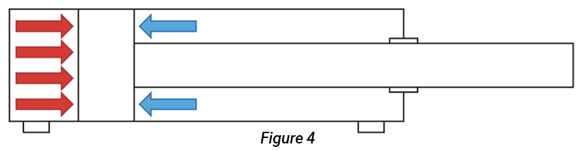
When working with cylinders with any cushion, it is vital to consider the possibility of pressure intensification. To reduce the cylinder speed, the exiting flow must be restricted so that the incoming flow reaches the maximum pressure. However, because of the area difference on each side of the piston, the exiting flow will not be the same pressure as the incoming flow. On the extend side, also known as the blind or cap end, the fluid under pressure acts on the full bore diameter of the cylinder. On the retract or rod side, the fluid under pressure does not act on the center area because of the rod; it only acts on the annular area between the rod and the bore. The ratio of the extend area to the retract area is known as the cylinder ratio. The cylinder ratio is typically in the range of 2:1 to 3:1, but if the rod is large relative to the bore, it can be as high as 10:1 (figure 4).
If the pressure is controlled by a main system relief set at 3,000 psi (207 bar) and the cylinder has a ratio of 2:1, when the cylinder is retracting and the cushion is active, the rod side pressure increases to 3,000 psi (207 bar). Because the extend side area is greater by a factor of two, the resulting pressure on the extend side is calculated by dividing by two, or 1,500 psi (103 bar).
This pressure is used to design the control orifice size in the piston for the designed flow rate. If the same cylinder has a cushion at full extend and the extend side pressure increases to 3,000 psi (207 bar), the resulting pressure on the rod side is 6,000 psi (414 bar). This higher pressure is completely contained within the cylinder and is not measured with a cylinder port gauge, nor can it be prevented or limited with the addition of an external relief valve.
In addition to using this pressure to determine the orifice diameter, this higher pressure must also be considered when selecting seals, tube-wall thickness, and head retention methods to prevent cylinder failure. If the cylinder has a relatively large diameter rod and therefore a high cylinder ratio, even at low system pressures it may not be economically feasible to design the cylinder for the resulting rod-side pressure. It may be necessary to add a relief valve set at a lower pressure specifically for the extend side of the cylinder. If that does not provide adequate extend force, the cylinder may not be a good candidate for a cushion at full extend, and deceleration should be accomplished by a different method.
Although removing the potential for incorrect adjustment may be a benefit in some applications, in others the benefits of adjustment outweigh the risk. For these applications, it is possible to adapt the cushion piston design to accommodate an adjustment valve in the end cap or head gland.
As with all hydraulic components, the introduction of a control orifice makes it more sensitive to contamination. A small particle can lodge in the orifice and block or restrict flow, negatively affecting cushion performance. It is important for proper operation and long life to maintain a high level of fluid cleanliness via proper filtration.
A race car on a track can stop one of two ways. If the driver applies the brakes, the reduction in speed is controlled and gradual as the brakes convert the energy to heat and the heat is dissipated. If the car hits the wall, the change in speed is abrupt and violent. The car will likely sustain mechanical damage as it absorbs the change in energy. A welded cylinder with a properly designed cushion piston is analogous to properly applied brakes, as the energy is transferred to hydraulic heat and the cylinder stops in a controlled manner. This can provide a significant benefit to the machine and the user.
Illustrations in this article are by Aggressive Hydraulics.
Share this information.
Related Posts

Offshore Technology Conference 2016
New Safety Brake for Small Wind Turbines

Tailoring Comprehensive Filtration Programs to Meet Your Needs

OTC Anchors in Houston for Marine Confab
Transforming Fluid Power: My Torque Isn’t Working
If a Picture is Worth a Thousand Words, How Many Words is an “Animated” Picture Worth?
Sponsor

Sponsors