Partnering with Manufacturers to Achieve Energy Savings

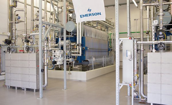
SMC Corp. of America, a supplier of factory automation components, has been working with manufacturers for nearly a decade to reduce their compressed air costs. The program’s goals are to assist customers with resource conservation efforts, raise awareness of available energy-saving measures, and develop products suitable for reducing compressed air costs while increasing productivity.
The company offers an extensive list of products designed to reduce energy consumption and lower the cost of ownership of automated machinery. These products can be applied at the Original Equipment Manufacturer (OEM) level, as well as retrofitted to existing machinery. The following general guidelines should be observed:
• Near the air inlet, there should be an identification plate showing
- the minimum air pressure required,
- the average air consumption per machine cycle, and
- the required flow rate (peak air flow).
• If an air-quality standard for water content (pressure dew point) is called for, that qualifier should be noted on the identification plate, as well.
• The machine should be designed to operate with an air pressure as low as reasonable.
• Verify that the end user will have the compressed air capacity available to operate properly.
• If there are limited applications within the machine that require a higher pressure, consider the use of a booster to supply flow to just those locations.
• The operating program should include measures that will automatically shut off the inlet air during prolonged downtime.
Air Preparation
• A 3-port shut-off valve with lock-out/tag-out should be included to remove inlet pressure during maintenance or extended downtime.
• A water-removal filter should be included to remove any water that might be present in the air lines.
• Inlet air filters should
- be sized for pressure drop across the element less than 3 psi,
- meet the filtration rating determined by the component supplier,
- be equipped with an automatic drain to reduce routine maintenance,
- be designed to indicate when the element should be replaced, and
- if necessary, include a coalescing filter and/or odor-removal filter.
• Pressure regulators should be tamper resistant to avoid inappropriate changes.
• If air pressures will need to be changed often, use an electro-pneumatic regulator controlled by the machine’s PLC.
• A final safety valve should include a combination E-stop, quick exhaust, soft start, and a second lock-out/tag-out.
• If shutdown redundancy per ISO 13849-1 is required, consider a Category 3 and Category 4 safety shut-off valve.
• If the compressed air is lubricated, a re-classifier can be included to capture and contain the entrained oil rather than exhausting it to the work area.
Sustainability
• Install an ALDS (Automatic Leak Detection System) that will cycle through the pneumatic system during downtime, measuring and recording any air leaks found at the component level.
OR
• Install flow meters and pressure switches at the air inlet to measure and record air usage.
OR
• At minimum, flow meters and pressure switches should be installed on start-up to document initial air usage. Those start-up numbers can be compared with later measurements of air usage to determine if machine efficiencies have degraded over time.
Air Power Components
- Minimize the distance between the directional control valves and the actuators to reduce wasted air volume.
- Use tamper-resistant flow control valves on the actuators.
- Include residual pressure-release valves at select locations for manual relief of trapped air pressures.
- If the flow-control valves need to be adjusted often, consider the use of electronically controlled proportional valves operated by the machine’s controller.
- If significant areas of the machine can operate at lower pressures, install regulators to reduce pressure to those areas.
- If the machine will be subject to wash down, specify epoxy-coated or stainless steel components.
- Any air blow should include an engineered nozzle, a pressure regulator set for optimum impact force, and a solenoid valve to shut off the air supply during idle time.
- Blowguns, if included, should be of an efficient design and meet OSHA requirements.
- Low-wattage coils (0.5 watts or less) should be employed on all solenoid valves.
- If actuators require thrust in one direction only, investigate lowering pressure on the return stroke. Alternative speed/pressure control valves may need to be included.
- If a machine failure might result in a cylinder causing tooling/product damage or operator injury, examine a fine-lock or end-lock option.
- Always include a high-quality muffler on all air exhausts to minimize noise.
Vacuum Components
• Venturi-style vacuum ejectors can be employed in non-continuous applications, but they should include the following:
- A tamper-resistant regulator
- Warning when air pressure exceeds optimum (usually 65 psi)
- Multiple-stage vacuum ejectors for best efficiency
- Vacuum switches as part of a control system used to shut off the air supply when the part is adsorbed and restore airflow if the vacuum pressure degrades
- Vacuum-saving valves to isolate a failed pad within a multi-pad application
- Minimal distance between the ejector and the end effector in order to reduce line volumes
Any program designed to reduce compressed air consumption has to work at all levels. Training needs to address awareness and promote a cultural shift from “production at all costs” to “let’s reduce our production costs.” Existing machines need to be evaluated and improved so that operating costs are kept in check. New machines need to be designed and specified with not only productivity goals, but also energy targets in mind. Total cost of ownership, sustainability, reliability, and productivity all need to be defined whenever machines are put into production.
For more information: This article is an excerpt based on a presentation at the 2013 Fluid Power Systems Conference held in Rosemont, Ill., from November 19-21, 2013. Make plans to attend the next Fluid Power Systems Conference in Spring 2015!
About the Author: Jon Jensen, CFPPS, CFPECS, CFPAI, is the Energy Conservation Group manager for SMC Corp. of America, a past president of IFPS, and the chair of the Curriculum Committee for the Energy Efficient Hydraulics and Pneumatics Conference (now the Fluid Power Systems Conference). Prior to managing the Energy Conservation Group, Jon served for nearly 10 years as SMC’s North American training manager. He can be reached at jjensen@smcusa.com.
Reinforce your industry expertise with a Pneumatic Mechanic, Technician, or Specialist certification. Apply online at www.ifps.org.
Share this information.
Related Posts

Sponsor

Sponsors