Vacuum Control Valves & Actuators
The following is an opinion article written by Dane Spivak of Davasol Incorporated, an industrial brand management firm with many clients. This article is written in partnership with one client, Vacuforce LLC based in Indianapolis, IN, USA.
If you have any questions, contact Dane Spivak at dspivak@davasol.com

Figure 1: 2/2 (2-way) normally closed spring return vacuum valve
INTRODUCTION
In fluid power systems, valves are commonly used to control the tools and output of machines. Many models, sizes, and types exist to offer numerous control capabilities. Vacuum shares this same concept where valves are primarily used to turn a vacuum on and off, or to relieve and maintain pressure. The following article is a general overview of vacuum control valves and their use in manufacturing production facilities.
2/2 AND 3/2 TYPES
The most popular vacuum valve models are 2/2 and 3/2 (2-way and 3-way). The first number represents the number of ports and the second indicates the number of valve positions. Ports/positions notation is the standard designation to identify the basic functionality of a valve. For arguments sake, let’s consider all valves in the following content to be spring return as they are by far the most common in vacuum applications.
2/2 valves have two ports and two positions. The 2/2 model can be thought of simply as a “stop and go” valve. In one position, the valve is closed and vacuum is OFF, and in the other position, the valve is open and vacuum is ON. If the rest position of the valve is closed, the valve is referred to as normally closed (NC), whereas normally opened (NO) is the opposite. A normally closed unit requires the valve to be energized to open and turn the vacuum on. The choice of NC or NO is usually decided based on safety requirements of the system. During a power loss, the valve rest position is key to determine how the system will react. Figure 1 shows a typical 2/2 valve and its symbol. An example of a 2/2 valve application would be turning the vacuum on periodically to increase the vacuum level in a storage tank.
3/2 valves have three ports and two positions. They turn the vacuum on and off just like the aforementioned 2/2 valve, but there is a third port to exhaust vacuum from the application. If we consider a normally closed 3/2 valve, the vacuum source is closed off while the application is open to atmospheric air. If the valve is energized, it changes positions so that the vacuum source is connected to the application and the exhaust port is blocked off. If we then de-energize the valve, the vacuum source is shut off and the application opens to the exhaust. During this transition, atmospheric air is introduced to the application and the vacuum decays. The normally opened version would have the reverse conditions.
Figure 2 shows two 3/2 valves and their symbols.. Direct acting and pilot assisted actuators will be covered in the following section. An example of a 3/2 valve application would be using vacuum cups in a pick-and-place system where vacuum needs to be applied to the cups to lift the part, then exhausted to release.
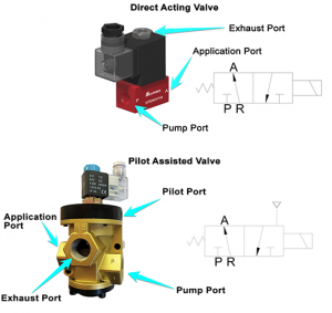
Figure 2: Direct-acting and pilot-assisted 3/2 (3-way) vacuum valves
DIRECT-ACTING vs PILOT-OPERATED ACTUATION
Vacuum valves can be direct-acting or pilot-operated. Direct-acting valves are energized and switch positions using energy solely from the powered solenoid. Pilot-operated valves use assistance from compressed air to shift valve positions.
Direct-acting types are typical for smaller valves where a relatively smaller coil can be used to shift valve positions. If the energy required to change positions is reasonably low, the power from the solenoid alone can be used. As valve size increases, the energy required to shift positions increases. Particularly under vacuum since the suction pressure is applying a counter-pull force on the actuator. The larger the actuator area, the more vacuum force is applied, and the more energy is required to overcome it.
Therefore, as the valve size increases, a larger coil is needed or another means of energy can be introduced to allow the valve to shift positions. This is where the compressed air pilot assistance is required. To counter the vacuum and spring force applied to the actuator, compressed air is used as the energy source to push the actuator to change positions. This design allows for a reduction in coil power. Refer back to Figure 2. It shows two 3-way valves, one is direct-acting and the other has an external air pilot as the motive force.
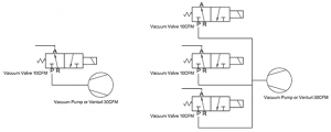
Figure 3: Vacuum valve circuit designs with restricted and efficient flows
SIZING A VACUUM VALVE
The first step in selecting a valve is to ensure it is vacuum rated. Depending on the internal design and actuation capabilities discussed previously, a valve may or may not be capable of working under a vacuum. Valve manufacturers provide pressure ratings and will generally state if a valve is compatible with a vacuum.
It is tempting to choose a valve based on its port sizes to match the surrounding components in the system, however it is not necessarily an ideal approach. Vacuum valves should be sized according to their flow ratings to ensure the flow is not being restricted. For example, it is counterintuitive to use a single valve with a flow rating of 10CFM if the pump is producing 30CFM just because the port sizes are equal and convenient. However, using this same example, three valves in parallel will manage 30CFM and allow full efficiency for the selected components. The circuits shown in Figure 3 demonstrate this design approach. Alternatively, a single 30CFM valve would also be acceptable.
Valves specifically designed for a vacuum should have much larger orifices compared to a pneumatic valve. Because of the higher pressures generally associated with standard pneumatic valves, a relatively large pressure drop may still provide an adequate flow. Vacuum valves have a maximum pressure differential of less than one atmosphere. An acceptable restriction in a standard valve may be too great for a vacuum application, drastically limiting vacuum flow. This is due not to the port sizes, but the internal orifice within the valve. A typical direct acting pneumatic ½” ported valve will have a 2mm orifice, whereas the same valve configuration for a vacuum will have a 12mm diameter orifice. That’s a surface area multiple of 36 (3.14mm² vs 113mm²).
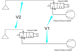
Figure 4: Vacuum valve locations
VALVE LOCATION
The vacuum valve separates the upstream and downstream volumes in a system, so its location affects the performance of the application. If we consider an application with a fixed pump position, a vacuum valve installed closer to the application will result in quicker cycle times. (Refer to Figure 4.) To increase the application speed, the goal is to reduce the volume on the application side (V2) so there is less air to evacuate. This also means there is less volume to exhaust, which further reduces cycle time as well. Additionally, the volume between the valve and the pump (V1) acts as a vacuum reservoir so by decreasing the application side volume (V2), the pump side volume (V1) is increased acting as a larger vacuum reservoir.
Placing the valve closer to the application can be advantageous in high-speed vacuum systems such as pick-and-place in the packaging industry, where rates can be over 100 cycles per minute. On the other hand, the valve location in slower systems can prove to be insignificant, such as slow vacuum pick-and-place palletizing machines where only 5 cycles per minute is required.
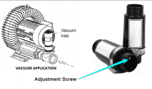
Figure 5: Vacuum relief valves
RELIEF VALVES
The concept of a vacuum relief valve is quite simple. When the vacuum level is high (low absolute pressure), the valve opens and allows atmospheric air to bleed into the vacuum system to maintain a steady or lower vacuum level. Relief valves are often used in conjunction with regenerative blower pumps to prevent them from going into “over pressure” and overheating, but can also be used for general-purpose vacuum relief. One example would be for gripping a delicate part with a vacuum cup. If high-vacuum level pressure causes damage to the part, the vacuum relief valve can be used to meter and lower the maximum vacuum level. Relief valves are often factory preset, but many have an adjustable mechanism to change the pressure relief setting. Figure 5 shows an example of a relief valve.
CONCLUSION
There are many types, designs, and purposes for vacuum valves and selecting the appropriate model can have a major impact on the application. This article reviewed concepts and strategies to help guide the reader to a better understanding of vacuum valves in general. Each application is unique and professional assistance should be considered when selecting a vacuum valve.
KEYWORDS
The keywords below are self-defined to help the reader best understand this article. The definitions are described to reflect the relevancy to vacuum valves.
Vacuum pressure: A pressure lower than atmospheric in a known volume. Sometimes referred to as negative pressure, away from zero pressure, or vacuum level.
Rest position: The position and condition of the valve when energy to actuator is not applied.
Spring return: When a valve is de-energized, a spring return valve uses a spring to shift back to its rest (normal) position.
Solenoid: Portion of a valve which provides electromagnetic energy.
Coil: Sometimes referred to as a synonym to solenoid, the coil is the physical part that fits onto the valve to produce the electromagnetic energy.
Actuator: The physical device that causes the valve to operate or shift positions.
CFM: Cubic feet per minute – Common unit of measurement for flow rate in North America.
Psig: Pounds per square inch pressure shown on a gauge. Atmospheric pressure being zero.
Share this information.
Related Posts
Pressure and Temperature Controls Support Booming Shale Gas Extraction Industry
Case Study: Filtering Lube Oil in Siberia – In Winter!

Transforming Applications
Research to Watch: Investigation of Noise Transmission through Pump Casing

Fluid Power Journal and IFPS to Release 2013 Salary Survey
Telescopic Handler Doubles Lifespan with Innovative Repair Design
Sponsor

Sponsors