Performing Load Calculations
Understand Linear Load and Motion Parameters
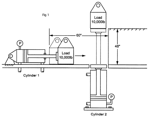
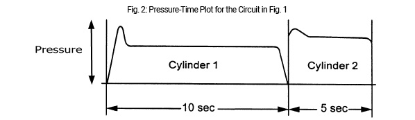
Fig. 1 illustrates two cylinders being used in a hydraulic system. Cylinder 1 moves the load horizontally and cylinder 2 lifts the load vertically. The pressure-time plot of both cylinders extending is shown in Fig. 2. When cylinder 1 extends to move the load horizontally, the pressure curve spikes up at the beginning as breakaway forces, an effect of static friction (sometimes called stiction), are overcome and the load begins to move. An additional force to be considered is the force of acceleration. The initial pressure curve is followed by a straight horizontal line, representing a constant state force, as the load is pushed over to cylinder 2. The horizontal pressure line drops back to zero when cylinder 1 stops extending. When cylinder 2 begins to extend, the pressure line spikes slightly, as stiction in the cylinder and the force of acceleration are overcome. Thereafter the pressure line becomes horizontal, remaining slightly below the initial pressure level when the cylinder comes to rest at the end of the stroke because the cylinder is still supporting the load. In the pressure-time plot in Fig. 2, cylinder 1 extends under load for 10 sec., while cylinder 2 extends under load for 5 sec.
Design calculations follow for the extension stroke of the cylinders in Fig. 1.
Step 1: Select the system pressure. The relief valve pressure will be set at 2,500 psi.
Step 2: Size the actuators to move the load at less than system pressure.
Friction is the resistance that one surface or object encounters when moving against another. In other words, it is a resistance to movement as one surface attempts to slide against another. This includes the hydraulic fluid sliding against the walls of the plumbing, the rotating groups of pumps and motors, the valve spools and poppets, and the pistons within cylinders. Friction is also a factor in the objects that are being moved by hydraulic equipment. There are charts that provide the coefficient of friction for various materials. In calculating the force required to move an object across a surface, there will be a given coefficient of friction that will be multiplied by the felt weight of the object being moved. When an object is moved on an incline, the felt weight of the object will be lower than the actual weight, based on the angle of incline.
The weight of the load on cylinder 1 is 10,000 lb. There is a coefficient of friction of 0.4. The load will be moved through a stroke of 60 in. Multiplying the weight of the object by the coefficient of friction gives a load of 4,000 lb. that must be moved.
In order to keep the pressure in cylinder 1 below 2,500 psi, a 2 in. bore cylinder is selected. In this example, it is assumed that the rod would have sufficient rigidity (column strength) such that rod sagging or buckling will not be a factor through the 60 in. stroke.
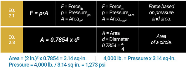
Solve for the pressure in the extending cylinder using Eq. 2.1 and Eq. 2.8:
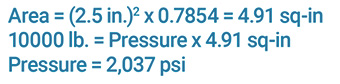
Next, solve for the pressure required by cylinder 2 to balance the load using a 2.5 in. bore cylinder X 48 in. stroke. Again, it is assumed the cylinder applies only the lifting force and that friction is not a factor. In actual practice, a margin is added in order to allow for system losses, friction, and the force of acceleration. Since these factors can vary greatly, depending on the system dynamics, the static pressure required to balance the load shall be used in these calculations and on the exam.
The pressure setting of the relief valve or compensator must be tailored to the circuit so that it is not too close to the working pressure in order to prevent instability in the system.
Cylinders with smaller bores could have been selected without exceeding 2,500 psi, but friction and inertia will cause the pressure to increase to higher levels. The friction that must be overcome is caused by several factors. One factor is the mechanical friction between the dynamic seals of the cylinder and the cylinder walls and rod. In addition, as the fluid flows through the fluid conductors, pressure will drop as a function of both the internal friction of the fluid as well as the friction between the fluid and the walls of the conductors. As fluid velocity increases, and as the number of bends in the conductors increases, pressure drop increases. This pressure drop is a measure of the amount of fluid friction evident in the system. Good system design strives to minimize this pressure drop. For these calculations and those on the exam, losses due to mechanical and fluid friction shall be ignored unless they are specifically included in the problem.
Step 3: Plot the work cycle, calculate flow rates, and size components.
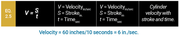
The cylinder extension portion of the work cycle is shown in Fig. 2. Before calculating the flow rate required to extend the cylinder, the velocity of the cylinder must be calculated. For cylinder 1, solve Equation 2.5 for this value:
Calculation of flow rate to a cylinder is given by either 2-9 or 2-10:
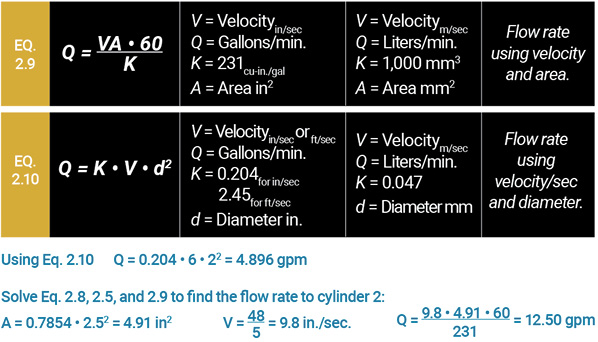
Thus the pump would have to supply 4.90 gpm to cylinder 1, and 12.5 gpm to cylinder 2. If the idle portion of the cycle were longer than the work portion of the cycle, a 13 gpm fixed displacement pump would be efficient at the larger flow rate, but would dump approximately half its flow over the relief valve while extending cylinder 1. One way to solve this problem would be to use a double pump arrangement with 5 gpm and 13 gpm pump segments. This would be similar to the application of steering and implement pump segments used on field tractors.
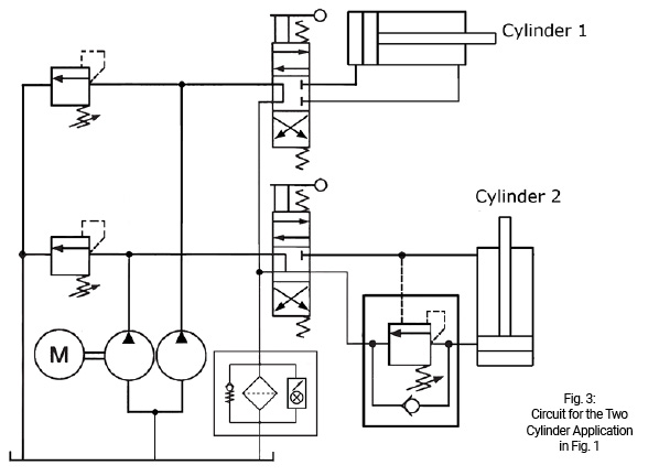
Fig. 3 shows a circuit for the two cylinders that uses a fixed displacement double pump, two manually operated 4/3 (four way, three position) directional control valves, and a counterbalance valve for cylinder 2 to prevent the load from dropping.
Test Your Skills
1. What would be the velocity in meters per sec. of a cylinder traveling 1,200 mm in 4 sec.?
a. 0.03 meters per sec.
b. 0.30 meters per sec.
c. 3.0 meters per sec.
d. 30.0 meters per sec.
e. 300.0 meters per sec.
2. A pump operating at 1,750 rpm is used to extend a 4 in. bore x 2 in. diameter rod x 24 in. stroke cylinder at an average velocity of 9 in./sec. What is the theoretical displacement of the pump?
a. 0.62 in3/rev.
b. 0.97 in3/rev.
c. 1.23 in3/rev.
d. 2.91 in3/rev.
e. 3.88 in3/rev.
What is the correct solution?
- b
- e
Share this information.
Related Posts


2 thoughts on “Performing Load Calculations”
Leave a Reply
Sponsor

Sponsors
We had problem in our plant that, a vertical cap end flange mounted hydraulic cylinder having a bore 125 mm 90mm rod and 660 mm stroke is not lifting a 10 ton weight in 90 bar pressure. In hydraulic circuit there is counter balancing valve and J Type f double solenoid valve. Initially in works fine but now not working. Please help us to come out of this problem.
It was interesting when you explained how different hydraulic cylinders lift the load horizontally and vertically. My uncle is looking for a hydraulic equipment supplier to work with since he’s in the process of developing a new manufacturing plant. I’ll have to share this info so he can be more informed about how hydraulic cylinders work and ask more specific questions to potential suppliers!