Pneumatics and Machine Design

This article is a bullet-point summary of pneumatics and basic machine design considerations when using pneumatic technology. It is not intended as a comprehensive guide or a replacement for individual sizing and selection requirements of pneumatic components.
Some Important Properties of Air
Contents of Atmospheric Air
The air at a compressor’s intake contains about 78% nitrogen, 21% oxygen, 0.9% argon, and other trace gases. Most importantly, it also contains varying amounts of dust, pollen, other airborne contaminants and water. Depending on the environment, lots of dirt and water are possible. Dirt is an abrasive, and water is a solvent. They have to be removed at point of compression, and failing to do so will cause major problems.
- Use an “after cooler” with automatic drain immediately after the compressor if not built in.
- Use an air tank with automatic drain. This component stores energy, allowing the compressor to run cooler and less often, extending life. It also serves as a heat exchanger to eliminate additional condensate.
- Use a main line filter with automatic drain next in-line. Over-capacity at this point is far better than under-capacity.
- Use a refrigerated dryer with automatic drain after the main line filter.
- Use plumbing practices to inhibit the transmission of water and materials that inhibit the formation of corrosion.
- Use correct “point-of-use” filtration.
- If control of the compressed air supply is not a possibility, use additional filtration and automatic drains at point of use on the machine. Note an acceptable air-cleanliness standard for the machine (reference ISO 8573-1) and base warranty information upon the use of clean, dry air.
Compressibility and Volumes
One advantage of compressing gas molecules, (i.e. “air”), squeezing them together, is storage. A large quantity of potential energy can be stored in a tank. A disadvantage is the lack of density that makes the precise positioning of air cylinders difficult and simultaneous operation virtually impossible. Because compressed air is a “soft” form of energy, the correct application of volume becomes a critical performance issue when using pneumatics.
- Use a tank to store additional energy to compensate for momentary lack of supply pressure or momentary increases in flow demand.
- Use a tank as a “buffer” when air pulsations cause issues with performance of cylinders, gauges, filter life, or regulator life. When regulators are paired with small tanks, performance gains can be realized.
- Reduce circuit volume that compromises performance by mounting valves as close as possible to cylinders, rotary actuators, or other “end effectors,” but ensure enough flow capacity is available in any connectors and tubing.
- Do not design the use of more than one cylinder to move a common load unless the load has external guides. Multiple pneumatic cylinders cannot be accurately coordinated for speed or position. The resulting imbalanced load will accelerate wear and may cause malfunction or even a catastrophic failure.
Pressure Characteristics
Pneumatic pressure is expressed as a measure of force per unit of area. It literally represents the amount force created by the number of air molecules in random motion striking a surface of a known size. In the ocean of air we live inside, atmospheric pressure is approximately 14.696 pounds of force for every square inch at sea level. In pneumatic systems, the air is concentrated (compressed), so more molecules are striking the same amount of area.
The safe, economical, and practical amount of pressure that should be used for an application is a primary consideration in the selection of pneumatics. Pressurized air must also be visualized as and equated to a directly proportional relationship of potential energy, kinetic energy, and money. The higher the pressure, the higher the stored energy and the energy turned into power, but at increasing cost. Think of all three at the same time during the design process.
- Use the correct load ratio for pneumatic actuators.
- Use only the amount of pressure required for the force needed to do the work.
- Use regulators with performance characteristics that meet the requirements of the application.
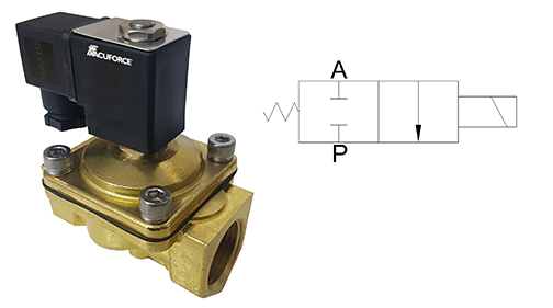
- A regulator is an on-demand valve that shuts off at the set point. Use as close as practical to the application.
- Use standard regulators on the supply side of a directional control valve unless otherwise noted (see “Energy Efficiency” later in this document).
- Size regulators in conjunction with filters by sizing the filter first.
Flow Characteristics
Flow is given as volume per unit of time, i.e. a cubic foot every minute (cfm or ft3/min). It is a measure of the rate that energy is being used by the end effector and is more correctly identified as “flow demand.” The maximum amount of flow required is the most important aspect of sizing virtually every pneumatic component upstream of the end effector and is called the “peak flow” demand.
Each pneumatic component, whether it be fittings, tubing, flow controls, valves, regulators, filters, and so forth, is sized based upon having enough “flow capacity” to deliver the “peak flow” demand without too much lost energy. This energy loss is called a “pressure drop” or “Delta P” and is the difference in pressure between the inlet of the component and outlet of the component during flow.
The “actual” pressure drop across a component in operation will vary due to a number of factors, so for purposes of sizing components, an “ideal” pressure drop is assumed for the flow capacity calculation. This assures sufficient flow capacity without under-sizing or grossly over-sizing the component.
The flow capacity is expressed as a comparative and unit-less number called a “Cv” or as an “effective area,” noted as the “S” value in mm2.
- Always calculate peak flow demand for each end effector in a machine.
- For multiple end effectors operating at the same time, peak flow demands can be summed.
- Size all pneumatic components based upon their flow capacity for the peak flow demand required.
- For tubing and piping size successively from small at point of use, to medium at transmission, to large at point of compression, sum the simultaneous peak flow demands common to each line.
- The longer the tubing or pipe, the less the flow capacity. Each 4-fold increase in length reduces the flow capacity by 1/2.
- For pneumatic logic, avoid long signal transmission lines if possible.
Energy Efficiency
- Eliminate waste by using precision nozzles, short pulses, and close target proximity to the nozzle(s) for blow-off applications.
- Shut off pressure to machines or processes not in operation for extended periods.
- Maintain and/or provide maintenance schedules for filters, regulators, lubricators, actuators, and all compressed air components.
- Use dual pressures. For example, a cylinder working in one direction but simply returning in the opposite should be operated with two pressures. A “check-type” regulator, or a check valve used in parallel with a regulator can be used between the cylinder and valve.
- Consider reducing machine or system pressure when the majority of applications are operated at lower pressures and only a few exist at higher pressures. Evaluate the use of an air pressure booster for the higher-pressure requirements.
Safety Considerations
There has been a lot written about this topic, but after 35 years in fluid power, I still see machines that present the danger of serious injury or death. We are responsible for each other, personally, professionally, and as fellow human beings. Never count on someone else to assure your safety. Never fail to account for the safety of others in your design. Make sure your design anticipates and protects against what could happen so you will know you have done all you could to keep people safe.
- Go to, read, and request information from www.osha.gov on safe machine design.
- Research, read, and review the machine design standard ISO 13849-1.
- Enlist help, other valued opinions, and critical analysis of any safety aspects of your design and validate them through established practices and comprehensive testing.
- Consider and/or employ the services of a PE (professional engineer) and/or firm specializing in safety analysis as needed for validation.
Never take safety for granted, ever.
About the Author: Richard Bullers, CFPPS, is senior applications engineer for SMC Corp. of America. He can be reached at rbullers@smcusa.com. Visit the company’s website at www.smcusa.com.
Share this information.
Related Posts
Vacuum Control Valves & Actuators
Identify Hose Assembly Terminal Ends and Determine Compatibility of Hose and Fittings
Why We Need a Global Standard to Measure Shifting Time of a Control Valve
The Negative Effects of Over-Pressurization

Fluid Power Student Club “Gives Back”

2014 IFPS Meeting – Charleston, SC
Sponsor

Sponsors