Screwed on Right: The Pros and Cons of JIC Hydraulic Fittings
 By Charles Kolstad, Marketing Manager, Tameson
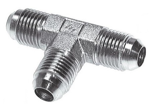
JIC fittings, also called SAE J514 hydraulic fittings, play an essential role in everyday applications. They are used extensively in agricultural equipment, the construction industry, heavy machinery, automotive industries, and more.
The fittings stem from AN fittings, which were developed by Parker then developed further by the U.S. military around the time of World War II. Developed by the U.S. Army and the U.S. Navy (hence “AN” in the name) for use in aviation applications, then further developed to high 3A/3B thread-class performance standards and tolerances, the popularity of the fittings quickly took off.
This article explores the origins, uses, and the pros and cons of JIC fittings and compares them to AN fittings.
In the aftermath of the World War II, many AN flared-fitting designs and specifications hit the market and caused confusion on which standard should be used where. Manufacturers need a specific standard.
The Joint Industry Conference standardized the AN design with a 2A/2B thread class to make manufacturing easier. The fitting became known as the JIC fitting. It delivered high performance at lower cost and a simpler manufacturing process than the AN fitting of the 3A/3B thread class.
The conference wanted the fitting standard to have the same reputation as the standards of the Society for Automotive Engineers International. SAE International represents over 100,000 engineers and experts in the aerospace, automotive, and commercial vehicle industries.
The conference persuaded a committee of SAE engineers to accept the task, and they were instrumental in developing the standard. In 1950, the SAE standard 37° flare fitting was incorporated into SAE J514. ISO 8434, replaced by ISO 8434-2 in 1996, became an ISO standard for the fittings in 1986.
The majority of JIC hydraulic fittings are used in the agriculture, construction, mining, and automotive industries. Despite not meeting the high-performance standards of AN fittings, SAE 37° 2A/2B UN/UNF series threads are designed for optimum thread fit that balances manufacturing capabilities, convenience, economy, and fastener performance.
Differences between JIC and AN fittings
JIC and AN fittings have always been similar in design, function, and size. However, there are considerable differences between them. One of the significant differences is economics. Due to the design factors, AN fittings are considerably more expensive. The price difference comes from being manufactured to tight design tolerances. It is also considered uneconomical to use AN fittings where the application does not demand them. There are also other main differences.
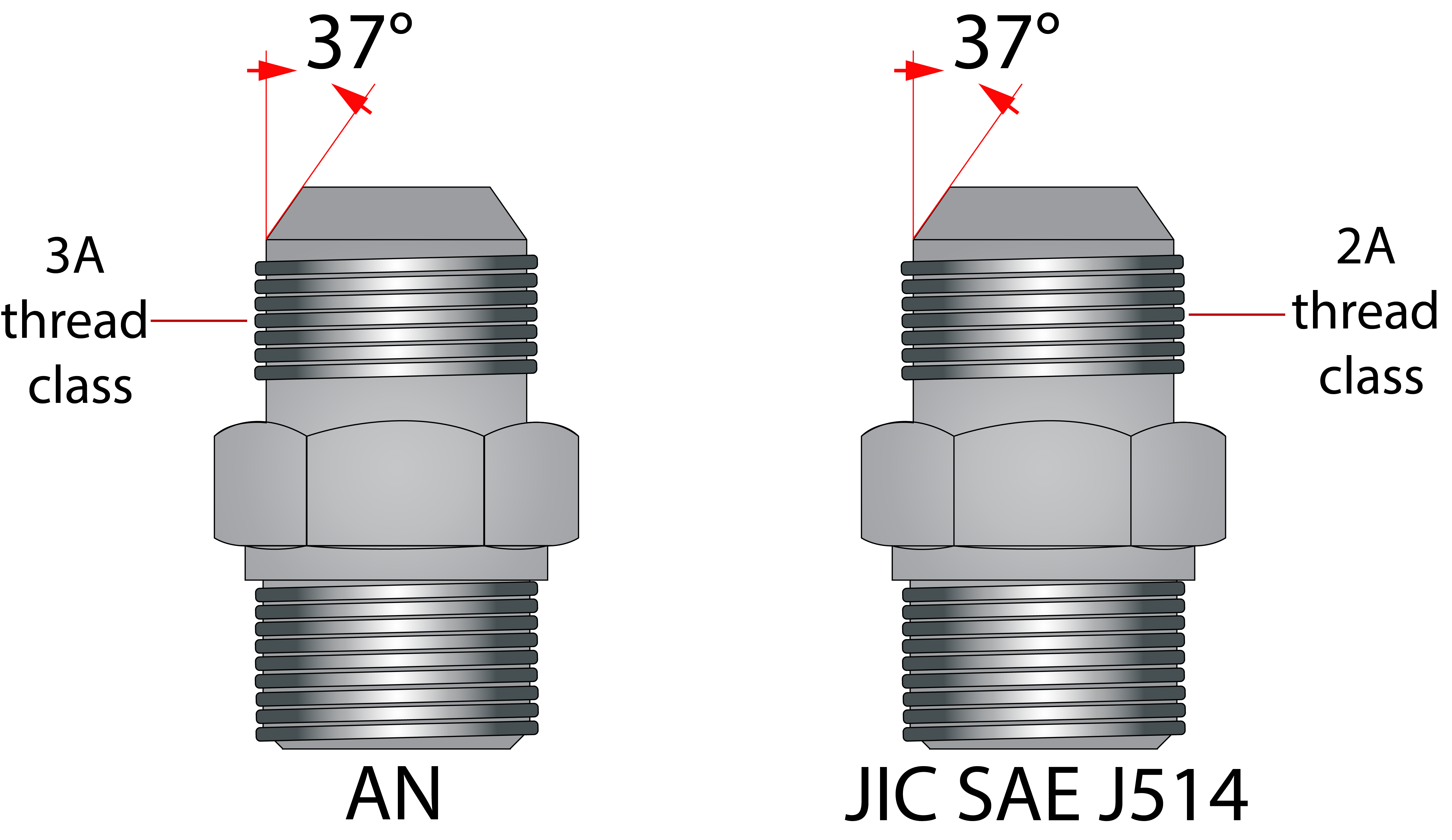
Threads. On AN 37° flare fittings, male and female fittings are produced to class 3A/3B UNJ/UNJF with a radiused root thread. J screw threads are made with a root radius, improving the tensile stress area of the fastener. It also reduces the stress concentration in the thread. Besides offering better fatigue life, it makes the thread considerably stronger, besides offering the benefit of better fatigue life and tighter for military, aerospace, and aircraft applications.
During the production of SAE 37° flare fittings, the male and female threads are made according to class 2A/2B UN/UNF. These fastener classes are designed for optimum thread fit that balances manufacturing capabilities, convenience, economy, and fastener performance.
Military vs. industrial standards. The AN flare fittings conform to the MIL-F-5509 specifications and the SAE aerospace (AS) standard AS4841. Fittings manufactured under SAE/ISO 37° conform to U.S. Department of Defense MIL-F-18866 and SAE J514/ISO 8434-2 standards.
Materials. Because of where AN fittings are used, they are commonly made out of more metals or composites of costly materials. SAE 37° flared fittings or JIC fittings do not have this requirement and are often made of more standard materials. AN fittings are available in carbon steel, stainless steel (CRES), aluminum, titanium, and copper-nickel. SAE 37° fittings are commonly made out of carbon steel, stainless steel, and brass.
JIC 37° flare fittings design. AN 37° flare and industrial 37° flare fittings function, operate, and look identical. It is not surprising that these fittings are sometimes used interchangeably. The male JIC fitting connects to a 37° female flare fitting or flared tube. The fitting seals through a metal-to-metal seal between the flared tube or the nose of the female and the male fitting. The relatively small seal area makes for a compact design, while JIC fittings benefit from a low-assembly torque, high-temperature and high-pressure capability.
Thread classes
As previously mentioned, JIC fittings according to SAE J514 are designed and fabricated according to the 2A/2B thread fit. Thread fit combines the allowances and tolerances between the male and female threads or how they fit into each other. In essence, it is a measure of tightness or looseness between the two. There are six standard classes for unified inch threads:
- 1A / 2A / 3A: The thread fit class standard for external or male threads.
- 1B / 2B / 3B: The thread fit class standard for internal or female threads.
All six classes are clearance fits. As the male and female fittings are joined, they assemble without interference. As the number increases, the tolerances between the threads become tighter.
- Classes 1A and 1B are considered to have highly loose tolerances. Assembly and disassembly can be done quickly and easily with this class. It is rare to specify this thread fit other than low-carbon threaded rod and machine screws.
- Classes 2A and 2B offers a balance between fastener performance, production efficiency, and economy. This thread fit is used in almost all commercial and industrial fasteners.
- Classes 3A and 3B should be used when tight tolerances are required. Safety is a critical consideration in the design of these fasteners. These fittings have very tight tolerances and no allowances.
UN or UNJ Threads
In North America, the Unified Thread Standard specifies thread forms and series, allowances, tolerances, and designations for screw threads. It standardizes bolts, nuts, and other threaded fasteners. On unified screw threads, the flank angle is 30°, and the threads are symmetrical. For this reason, they are commonly referred to as 60° threads.
UNC, UNF, and UNEF threads are almost identical to UNJ, UNJC, UNJF, and UNJEF threads. The letter J indicates that these screw threads have a much greater root radius (UNJ, UNJC, UNJF, and UNJEF). As a result, the tensile stress area of the fastener is improved, and the stress concentration factor in the thread is reduced. This leads to a stronger thread. Thread tolerances 3A/3B are standard for UNJ threads. Bolts with a UNJ thread root have a gentler curve that requires a shallower thread root. Since the thread root is so shallow, it cannot mate with a UN nut, so a UNJ nut is also specified.
Pros and cons of JIC fittings
Flared fittings are significantly superior to pipe fittings in terms of design and performance. Flared fittings have long been used instead of pipe fittings for most hydraulic design applications. There are several advantages to using flared JIC or J514 fittings. These include a wide selection of flared fittings in accordance with SAE J514 and availability in a variety of sizes and shapes. Because they were produced to the SAE J514 standard, they can be interchanged with the same product groups produced by different manufacturers, as long as they have been produced to the same standard. Also, they are suited for high-temperature applications because they are not fitted with an O-ring.
There are, however, some disadvantages to using JIC fittings. Specific applications (such as high-vibration applications) have a lower pressure rating than is required. These seals have a metal-on-metal construction, so they are only suitable for hydraulic, liquid, and noncritical applications. The assembly of the 37° flare fittings can cause some nose collapse, which is made worse by over tightening. In turn, this causes a reduction in flow diameter.
 Installing JIC fittings
JIC fittings should be installed using the flats-from-wrench-resistance method. This is a relatively simple way to check that the connection is torqued sufficiently without damaging the fit or thread. With the flats method, it is possible to eliminate the effects of plating, lubrication, and surface finishes on torque requirements.
Tighten JIC hose fittings properly with the following steps:
- Connect the female and male connectors and tighten with a wrench (about 30 lb.in. or 3.39 Newton meter) until you feel a slight resistance. This resistance determines the wrench resistance point.
- With a permanent marker, mark this position on both the male and female fittings.
- Using a JIC fittings chart, tighten the nut further according to the number of flats. One flat is equal to 1/6 of a turn on a hexagonal tube nut.
- Once the nut has been tightened to the required number of flats, mark the female and male connections again. It will also serve as a secondary reference point to check the tightness of the connection over time and serve as a reminder to reconnect after maintenance.
Knowledge of which fittings to use in an application helps ensure that the application runs smoothly and can help save money.
Share this information.
Related Posts


2 thoughts on “Screwed on Right: The Pros and Cons of JIC Hydraulic Fittings”
Leave a Reply
Sponsor

Sponsors
Dear Manager,
Yancheng Xinfujite Machinery Co.,Ltd. is a manufacturer specialized in hydraulic SAE flange and fittings for a variety of
hose,pipe and tube assemblies,The products widely used in petrol, the chemiacal industry, construction machinery and equipment.
Support for the hydraulic piping system.
Our Product group of SAE Flange including:
SAE Split flanges
SAE flange clamps
SAE weld flanges
SAE Butt weld flanges
SAE socket weld flanges
SAE socket weld elbow flanges
SAE threaded flanges/SAE threaded counter flanges
SAE BSPP threaded flanges
SAE NPT threaded flanges
SAE closed flanges/SAE Blind flanges
SAE blocks
All the above products of SAE flanges come in two main series
3000 psi standard pressure series, designed according to standard ISO 6162-1, this is also called code 61 flanges
6000 psi high pressure series, designed according to standard ISO 6162-2, this is also called code 62 flanges.
Materials of SAE hydraulic flanges
SAE flanges are usually available in Carbon steel, 304 stainless steel and 316 stainless steel,
other materials also can be supplied on request with some required min. order quantity.
In the new year, we have added forging joint blank equipment and several machining centers.
Welcome to inquire and place an order.
Best regards
Eileen Jia
Yancheng Xinfujit Machinery Co.,Ltd.
Contact person:Eileen Jia
Mobile:00 86 18262378752(wechat&WhatsApp)
Fax:00 86 515 86523666
E-mail:XF80@xfjt-saeflange.com
https://xfjt168.en.alibaba.com/
Address:No.8 2# Road Private Industrial Park Jianhu County,Yancheng city,
Jiangsu Province,China.
We are brass products manufacturing