Test Your Skills: Types and Applications of Compressors
The generic term “supply side” is often used to refer to the complete package that includes the compressor, drive motor, and associated hardware, as well as the filters and coolers used to remove the contaminants and water resulting from the compression process. Also included will be items such as the receiver and capacity control devices. In addition to selecting the size and type of compressor to be used, the following items need to be considered in the flow path as the air is transported from free air at the compressor inlet to the receiver prior to being dispersed to the points of use.
Location of the compressor. The foundation on which the compressor is mounted should be substantial enough to provide support and absorb vibration from the compressor. The base should permit the compressor to be mounted level and not subject to any deflection in the drive. The compressor room should also have the means to dissipate the heat generated by the compressors.
Compressor inlet location. The inlet temperature of the compressor can affect the delivery by almost 20%. Based on a normal intake temperature of 60°F, the compressor delivery will increase to 118% for an inlet temperature of -20°F and be reduced to 83.8% at an inlet air temperature of 160°F. Ideally the compressor inlet should be mounted outdoors at least six feet above the ground. It should be screened and protected from direct ingestion of rain, snow, and blowing dust or debris, as well as exposure to vermin. The intake should not be mounted directly adjacent to a wall or in a confined area to minimize vibrations caused by the intake pulsations. The intake piping should be adequately sized for the airflow and have minimal bends; any bends should be comprised of large radius elbows. The inlet filter should be mounted as close to the compressor as possible. The inlet filter protects the compressor from particles larger than
20 to 80 microns that may cause wear to rings and other close fitting parts.
Compressor discharge filtration. The compressor inlet filter is sized to eliminate contaminants that could damage the compressor. During compression the remaining particles have been concentrated as a function of the compression ratio. The compressor also introduces wear particles into the air stream and residual lubricating oil. Compressors that utilize oil as a cooling and sealing media will have a sump and separator to recover the compressor oil. Additional filtration will further remove contaminants, including particulates and residual compressor oils, after the air is cooled and the water removed.
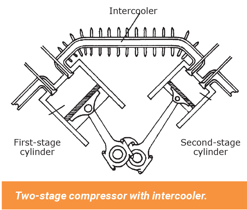
Cooling. During compression, air molecules become compressed and generate heat, which in turn reduces the volumetric efficiency of the compressor. Losses are kept to a minimum by dissipating the heat through fins on the compressor for air-cooled compressors or into the coolant for liquid-cooled compressors. The compressed gas also cools in the receiver. In a typical two-stage reciprocating piston compressor, a large first-stage piston feeds compressed air into a smaller second-stage piston. To improve volumetric efficiency, an intercooler cools the compressed air between stages. The intercooler often consists of a finned tube cooled by the flywheel fan. The heat of compression is transferred from the hot air to the core tube, to the fins, and then to atmosphere. Cooling is aided by the flywheel fan, which also cools the case, cylinder, and head of the compressor.
Compressor isolation. If a shutoff valve is installed in the discharge line to permit maintenance of the compressor without bleeding down the entire air system, an overpressure safety valve constructed to ASME standards must be installed upstream of the shutoff valve. A bleed-off valve should be installed to permit any residual pressure to be released prior to beginning maintenance. Follow proper lock-out tag-out procedures to ensure the compressor is not able to start inadvertently due to the normal air demand control sequence.
Water removal. Water vapor, which is held naturally in air, is compressed with the air and will precipitate out during the compression process. If unconditioned compressed air is sent downstream it will contaminate the piping system along the way with liquid water that drops out of suspension and enters air tools and machinery. For this reason the water must be removed. An aftercooler attached to the compressor outlet will remove most of the water before it gets into the piping system. In practice, aftercoolers placed immediately downstream of a compressor can remove approximately 85% of the moisture that passes through the compressor. For example, 1,000 cu-ft. of saturated air at 14.7 psia and 80°F contains about 1.58 lb. of water. Compressing that air to 100 psig and then cooling it back to 80°F will reduce the moisture content by about 90% to about 0.2 lb.
The receiver conditions air the same way. As air cools in the receiver, water condenses and falls to the bottom of the receiver, where it is drained off. Other methods used to further reduce the water content in compressed air include refrigeration or desiccants such as activated alumina. Sumps that collect the condensate must be designed so the drained fluid can be captured for proper disposal.
Compressor types
Air compressors commonly used for power and control functions are reciprocating piston, vane, rotary screw, lobe, scroll, and centrifugal types. A vacuum pump is treated as a compressor that works at less than atmospheric conditions. Within each of these types of compressors, additional distinction can be drawn for single-stage, dual-stage, or multiple-stage, and oil-injected or oil-less. In single-stage compressors the air p
asses through a single compression stage. The effective maximum compression ratio is 11:1 limiting effective outlet pressures to 1,030 kPa (150 psig.) In dual- or multi-stage compressors the air is passed into an additional compressor that further elevates the pressure. The air passes through an intercooler to reject some of the heat of compression to improve compressor efficiency. When discharge pressures of 1,750-2,400 kPa (250-350 psig) are required, two- or three-stage compressors are preferred. For extremely high pressures above 4 MPa (600 psig), four- or five-stage compressors will be used.
Reciprocating piston. The reciprocating piston compressor is similar in design to an internal combustion engine with a piston connected to the crankshaft by some form of connecting rod. The compressor can have multiple pistons and may be either single acting or double acting, resulting in compression strokes in both directions of the piston. Multi-stage compressors will connect the discharge from one cylinder though an intercooler to another cylinder of a smaller size to increase the compression ratio. Lubrication of the crank mechanism and pistons varies based on the design. For applications where trace amounts of oil are tolerated, the lubrication is similar to conventional internal combustion engines, using positive lubrication or the splash type commonly found on small engines. For oil-less or oil-free compressors the bearings will be prelubricated and sealed, the piston seals will be made of a low friction material that is self-lubricating and heat resistant. Valves identified as reed, disc, or strip are check valves that open with a very low differential pressure. Larger compressors may use an automotive style valve system driven off the crankshaft. Air cooling is the most common method, with liquid cooling limited to large compressors or those with high duty cycles.
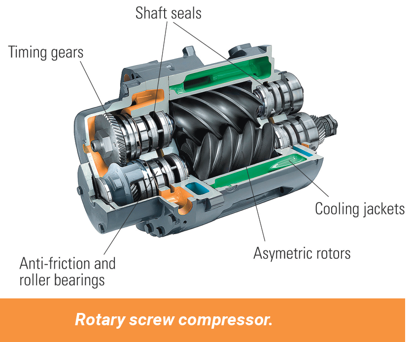
Rotary screw. According to the Compressed Air and Gas Institute, the oil-injected rotary screw compressor has become the dominant type of compressor for a wide variety of industrial and mining applications. The rotary screw compressor is a positive displacement device that utilizes two intermeshing helical rotors in a stator housing. The main rotor consists of a series of helical lobes that mesh precisely with the corresponding grooves in the secondary rotor. As the rotors turn, air that enters the inlet is transported progressively along the rotors away from the inlet to the discharge port. Oil is injected into the compression chamber to provide sealing, lubrication, and cooling. The oil used is typically a synthetic lubricant to provide long life at high compressor operating temperatures. The air-oil mixture leaving the compressor is then passed into a sump/separator to recover the oil, which is then filtered, cooled, and reinjected into the compression chamber. Oil-free rotary screw compressors utilize external gears to prevent the intermeshing rotors from making physical contact. The lack of oil for the sealing and cooling requires higher rotor speeds, and single-stage versions produce less air volume since none of the heat of compression is removed from the air during the process.
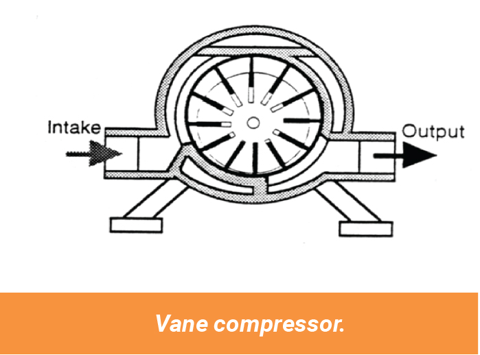
Vane. Sliding vane devices can be designed to operate as an air compressor or vacuum pump. Sliding vane compressors consist of a cylindrical stator with a smaller diameter rotor mounted eccentrically inside. The stator chamber is the same width as the rotor. The diameter difference of the rotor and stator and the thickness
of the chamber will determine the amount of air produced with each revolution of the rotor. The rotor has a number of slots fitted with vanes that are free to slide in and out. Driving the rotor causes the vanes to extend due to centrifugal force. The vanes form a seal against the inside diameter of the stator, the rotor, and the ends of the cylindrical stator. The inlet port allows air to be drawn in on the increasing volume side of the eccentric, where the vanes slide out of the rotor. As the chamber formed by two vanes, the rotor and the inside edge of the stator reaches the major diameter, the inlet port is blocked, and the discharge port is then opened as the chamber now passes to the decreasing volume area caused by the eccentric. The vanes are forced back into the rotor and the air is forced into the discharge port by the reduced volume. Oil is typically injected into the air stream to provide lubrication, cooling, and sealing of the moving parts.
Lobe. The twin lobe compressor uses gears to synchronize two intermeshing lobe-shaped rotors. The air is transported around the outside of the housing from the inlet to the outlet. The meshing of the rotor lobes forces the air out on the discharge side, while the separating of the lobes on the inlet side draws air into the pumping chamber. These compressors are typically used for large volumes of low-pressure air, or in transporting process gasses for scrubbers and similar applications.
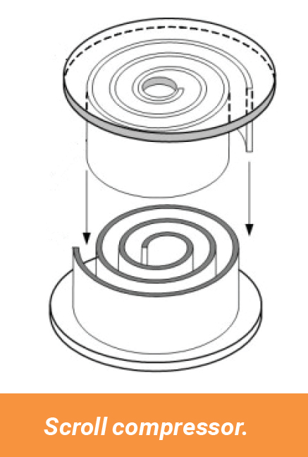
Scroll. The scroll compressor utilizes an oscillating spiral that fits inside a mating fixed spiral or scroll. The orbiting movement of the oscillating spiral creates a flow path that progressively moves from the inlet to the outlet. The precise shape and fit of the two scrolls provides a tight seal without actual metal-to-metal contact and does not require lubrication. The result is a continuous discharge of oil-free air with no pulsations and very low noise. Currently they are limited to 3.75 kW (5 hp).
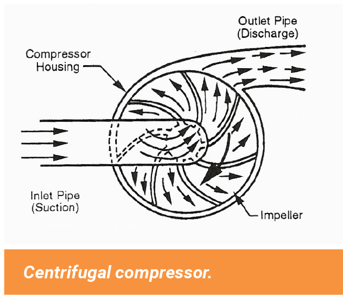
Centrifugal. Centrifugal compressors are usually used in large horsepower applications, typically above 300 hp. The centrifugal compressor is a nonpositive displacement compressor technically defined as a dynamic compressor. The air is accelerated and compressed as a result of impacting the rotating vanes or impellers. Stationary guide vanes are used to direct the airflow within the compressor. Multi-stage compressors may be inline on a single shaft with intercoolers located between the stages, or integrally geared consisting of a set of separate impellers and housings connected by a common drive gear. Performance of the centrifugal compressor is significantly affected by the discharge pressure and the rotational speed of the compressor.
Test Your Skills
1. Which of the following is the preferred location for the compressor inlet?
a. Inside the compressor room.
b. Inside the building close to the main demand location.
c. Outdoors at least 6 ft. (2 m) off the ground.
d.Outdoors close to a wall and an adjacent corner.
e. Indoors under a stairwell.
2. Which compressor type is defined as a dynamic compressor?
a. Centrifugal.
b.Reciprocating piston.
c. Rotary screw.
d. Vane.
e. Lobe.
See the Solutions
1-c and 2-a
Share this information.
Related Posts


Sponsor

Sponsors