Test Your Skills: Understanding the Operation of Servo Valves
Servo valves have been used to provide proportional control of fluid power systems long before proportional valves were developed. Servo valves are capable of a high degree of response and accuracy but are also very contamination-sensitive. In applications that do not require a high degree of precision or responsiveness, proportional valves have largely replaced servo valves due to the lower cost and lower contamination sensitivity.
Design and Performance Comparison of Servo and Proportional Valves: These two products have different characteristics and capabilities, and they offer distinct advantages (Fig. 5.10).
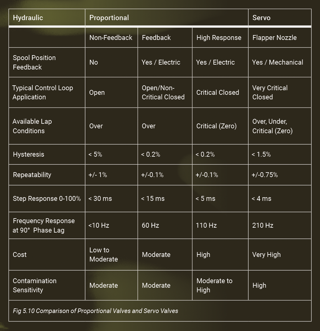
The values in Fig. 5.10 are for typical, commercially available, industrial-type proportional and servo valves of a similar size and nominal flow capacity. For a given application, these valves represent the increased performance that can be realized by applying an increasing level of technology. Valves with higher performance characteristics are available but tend to be application-specific and proprietary.
The most significant difference between proportional and servo valves is the method of spool actuation. Proportional valves are typically operated by a solenoid, which requires a relatively large power input. A force or torque motor in the servo valve requires little power input. The relatively large armature mass and considerable time constant associated with the coil mean that the proportional valves generally have poorer dynamic performance than servo valves of equivalent flow characteristics. Over the years, proportional valves have improved immensely with fewer performance differences. Proportional valves also provide substantial cost savings, however, they still do not replace the servo valves in high-end performance.
The basic servo valve produces a controlled flow proportional to an input current for a constant load. The major advantage is that load dynamics do not affect stability, unlike single-stage proportional valves. However, due to their close internal tolerances, servo valves are expensive and susceptible to contamination.
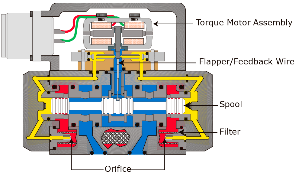
Fig. 5.11 Servo Valve (Flapper-Nozzle Type)
A very small electrical current (flow rate set-point) applied to the torque motor coils creates a magnetic force. This force swings the armature/flapper assembly to one side, restricting the fluid flow from one of the two nozzles (Fig. 5.11). This restriction of fluid quickly builds pressure on one end of the main spool, creating a difference in pressure between the two ends of the spool, causing it to move. This makes up the pilot stage of a two-stage valve. Thus, a relatively small amount of electrical power input sets up the ability for a relatively large hydraulic power output. Torque motors are special coils that produce a movement based on the signal polarity as well as the applied current, unlike proportional coils that produce the movement regardless of signal polarity. Wiring a torque motor backward will result in movement in the opposite direction.
The feedback spring deflects as the main spool moves. This deflection applies a force to the cantilever spring, creating a restoring torque on the armature/flapper assembly. Once the restoring torque becomes equal to the torque from the magnetic forces, the armature/flapper assembly moves back to the neutral position. This allows equal flow from the nozzles, generating equal pressures on each end of the spool and maintains this spool position until the command signal changes to a new level. Therefore, the spool position is proportional to the input current.
As the flapper/nozzle assembly sets up the pressure on either end of the main spool, causing the spool to move, the supply pressure flow from “P” port is open to one of the work ports, and the opposite work port is open to the tank (T) port. To achieve the maximum performance, the spool slides in a precision-matching sleeve containing slots or grooves connecting the spool lands and a flow path port between the appropriate ports. At the “null” position, the spool is centered in the sleeve, just covering the P and T port openings. Spool motion to either side of the null position allows fluid to flow. With a constant pressure drop across the valve, flow to the load is proportional to the spool position.
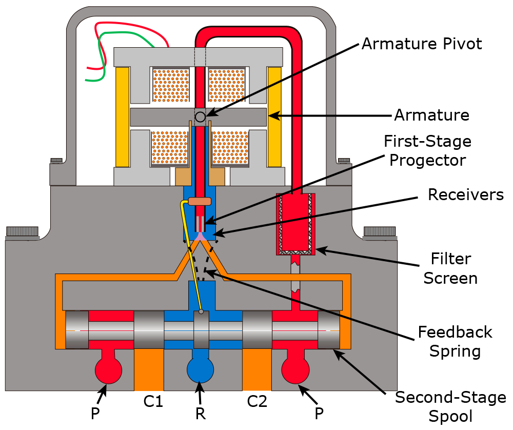
Fig. 5.12 Jet Pipe Servo Valve
Another common type of servo valve is the jet pipe design (Fig. 5.12). The pilot stage consists mainly of a torque motor, jet pipe, and receiver. A current through the coil displaces the jet pipe from its neutral position. This displacement, combined with the jet pipe’s unique shape, directs a focused fluid jet towards one side of the receiver. The jet now produces a pressure difference across the ends of the spool. This pressure difference causes a spool displacement, which, in turn, results in control port flow. The pilot-stage drain is through the annular area around the nozzle to tank.
The relative position of the edge of the spool land and the edge of the matching sleeve’s slot for the port opening is critical. This is known as spool timing, and in the centered null position, it is referred to as the spool lap condition. The three normal conditions are over-lapped, zero-lapped, and under-lapped spool designs (Fig. 5.13).
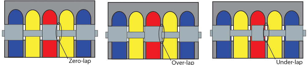
Fig. 5.13 Zero-lap, Over-lap, and Under-lap Spool Configurations
The over-lapped spool lands have additional (cover) material beyond the edge of the port. Therefore, the spool must move this distance from the null position before flow through the valve begins. This effect is called deadband. Once the spool land clears the edge of the port, the flow rate (Q) will be directly proportional to the amount of spool movement for a given pressure drop across the valve. The shape of the slots in the sleeve and whether there are notches in the spool lands will determine if this flow is linear. With over-lapped spools, there is a “minimum” input signal required to create flow through the valve. Any signal less than this minimum will not open the valve path ports, and the system will not be susceptible to small input or error signals.
Zero-lapped spool lands align precisely with the edge of the ports. Under-lapped spool lands do not fully cover the port in the null position. The amount of over-lap or under-lap is usually expressed as a percentage of the total spool movement or as a percentage of the full-input signal.
Under-lapped spools do not fully block the ports, so the actuator may drift if there is an external load when the hydraulic power is off. Loss of electrical control may also cause drifting.
The applications that require the higher performance of the servo valve also commonly utilize sensors to provide feedback to a controller. When diagnosing these applications, the control system must be reviewed as an entirety, not just component by component.
TEST YOUR SKILLS
1. Servo valves are used:
a. For applications when feedback is not available.
b. When the hydraulic fluid is highly contaminated.
c. When a low-cost solution is needed.
d. In applications requiring a high degree of precision or responsiveness.
e. Only for replacements on old machines.
2. An under-lapped spool:
a. Is over-sized to provide a tight fit in the housing bore.
b. Has spool lands that are wider than the ports to block the flow in the null position.
c. Has spool lands that match the port openings to block the flow in the null position.
d. Has spool lands that do not fully block the port when in the null position.
e. Is the result of removing the spool and polishing it with emery cloth to remove the scratches.
3. Which valve has the highest contamination sensitivity?
a. 4/3 directional valve with low-watt DC coils.
b. Non-feedback proportional valve.
c. Proportional valve with spool position feedback.
d. High-performance proportional valve with feedback.
e. Flapper-nozzle servo valve.
See Solutions
The correct answers are 1-d, 2-d, and 3-e.
Share this information.
Related Posts

Trelleborg Offers Quick Delivery of Standard O-rings

bauma CONEXPO India Announces Fair Dates
Freudenberg Polyurethane Meets Demands of Heavy-Duty Applications

MB Dynamics Introduces Test Bench for Brake Hydraulics

Kaman Distribution Group Celebrates 50th Anniversary
The Ultimate Guide to Keep Equipment Running in Cold Climates
Sponsor

Sponsors