Transforming Our Thinking About: Energy Units and Velocity

By Dan Helgerson, CFPAI/AJPP, CFPS, CFPECS, CFPSD, CFPMT, CFPCC
In the previous article, “Transforming Our Thinking About: Energy Units,” the energy unit was described as the unit pressure x the unit volume. The 1 cm3 charged with 1 MPa would be 1 cm3/MPa. This is also the description of the Nm. It could consist of 0.25 cm3 at 4 MPa or 10 cm3 at 0.1 MPa. In the U.S. Customary units, 1 in3 charged with 1 psi would be 1 psi/in3, or 1 in.lb. and could consist of 10 in3 at 0.1 psi or 0.25 in3 at 4 psi. We were shown that the Fixed Displacement Transformer (FDT) provided a more efficient way to synchronize the lifting and lowering of two cylinders having the same diameter, but with different loads. The FDT proportioned the energy units to the loads instead of simply proportioning the flow to the loads.
However, dividing and synchronizing flow is not the same as velocity control. The FDT did nothing to limit the speed of the cylinders. The speed was determined by the available flow rate from the source. The FDT proportionally divided the flow of energy units, but did not change the rate flow. For velocity control, the rate at which the energy units reach the actuators must be regulated.
An object at rest will stay at rest and an object in motion will stay in motion unless it is acted on by an external force. This resistance to change is called inertia. When accelerating a load, there is not only the inertia that needs to be overcome; there is also the resistance of other forces such as friction. In order to start to move a load, an acceleration force must be applied which is adequate to overcome all resistive forces. These acceleration forces are provided by the energy units. Pneumatic acceleration forces are typically provided by pressurized units of air stored, then released from a receiver. Hydraulic acceleration forces are provided by energy units stored in an accumulator or driven directly by a pump.
Effective pressure pE : The effective pressure is the difference between the input pressure and the resistive output pressure. According to the velocity equations, when the acceleration force exactly matches the resistive forces, a steady velocity is reached. With a fixed displacement motor or a cylinder, there is a discrete effective pressure that will produce a specific velocity.
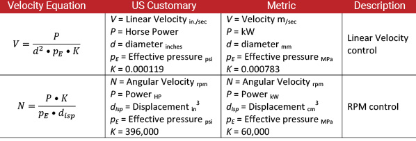
However, the specific acceleration force is difficult to calculate, and it is rare that the resistive forces are constant. To be able to maintain velocity, using either pneumatics or hydraulics, we supply more energy units than are required by the load, then add a controlled resistive load to counteract the excess acceleration. Typically, metering orifices are used to resist the extra energy units, control acceleration, and limit velocity. These metering orifices may be in the form of a simple disc with a drilled hole, a needle valve, a flow control with a bypass check, or a pressure compensated flow control where varying pressure differences will not change the actuator velocity. These devices enable us to maintain velocity control while providing units of fluid, either stored or directly driven, at higher than load pressures, in order to feed multiple actuators at varying pressures.
With pneumatics, meter-out orifices consume the extra energy units as the restive orifice exhausts the gas to atmosphere, allowing the air molecules to regain the heat lost in compression. The extra hydraulic energy units are consumed as the volume passes across the orifices and the excess energy, in the form of pressure, is removed as heat. In both cases, the extra energy becomes wasted energy.
One of the driving forces behind the development of the Variable Displacement Transformer (VDT) is its ability to provide the necessary resistive forces without consuming the extra energy.
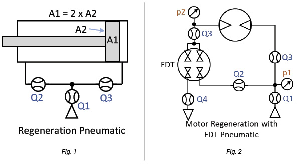
How does the VDT work? When used for velocity control, the VDT functions as a type of regenerative circuit. Most of us are familiar with regeneration circuits with cylinders. Using a 2:1 cylinder where the same pressurized fluid is directed to both the blind and rod ends, the cylinder will extend at twice the speed, but with half the force (Fig. 1). Regeneration doubled the flow to the cylinder, but no new energy was added. Doubling the speed requires a corresponding reduction in force. Every energy unit received from the source is used, but has been transformed to increase velocity.
The FDT can be used to regenerate the flow from a fluid motor (Fig. 2) and looking at the characteristics of the FDT will lay a foundation for understanding the VDT. Using a 50/50 FDT, half the motor exhaust is directed to atmosphere, and half is returned to the inlet, doubling the speed and halving the torque. Power-in must equal power-out and the FDT functioned as a pressure intensifier with flow Q4 exhausting to atmosphere: p2 x Q3 = p1 x Q2. Q2 = 0.5 Q3. Substituting, p2 x Q3 = 0.5p1 x Q3. p2 = 0.5p1. The FDT causes p2 to apply a resistive pressure on the motor that is half the input pressure. The resistive pressure is not wasted as heat, but instead, is used to drive the FDT and add half the flow to the inlet of the motor.
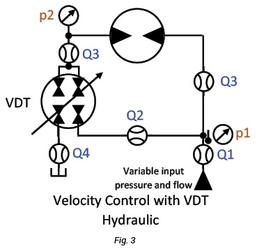 The VDT can do what the FDT cannot do. With a variable flow source such as from a receiver, a variable pump, or an accumulator, the VDT infinitely adjusts the proportioning of the energy units to match the desired velocity of the actuator (see Fig. 3).
The VDT is controlled by sensing the rpm or linear velocity of an actuator. Then, it provides a resistive load which produces an effective pressure (p1-p2) to match the load, but instead of consuming the extra energy, the unneeded energy units are returned to the actuator inlet. Only the energy units needed to do the work are drawn from the source. A desired velocity, angular or linear, can be established by the VDT without the use of a restrictive orifice.
For example: Given a pressure compensated pump set at 20 MPa (2,900 psi), a motor with a displacement of 50 cm3 (3.4 in3), a torque load of 80 Nm (708 in.lb.), and an rpm of 1550, what would be the effective pressure to control the rpm without a restrictive orifice?

From the Power equation, given the torque and rpm, we calculate the power to be 13 kW (17.4 hp). Inserting the known power into the equation

Then plugging the pE into the angular velocity equation

We see that an effective pressure of 10.05 MPa (1458 psi) will equate to 1550 rpm.
The motor will require 502.7 cm3/MPa energy units (4,447 in.lb.) to rotate 1 revolution. However, if the pump supplies all the flow, it will send 1,000 cm3/MPa energy units (8,845 in.lb.) to the motor and 497.5 cm3/MPa energy units (4,398 in.lb.) will have to be removed as heat, either before (meter-in) or after (meter-out) the motor. This is the effect of using the restrictive orifice.
The VDT provides the necessary resistance to the excess input pressure, but instead of discarding the energy as heat, the energy is used to drive the VDT as an intensifier, returning the energy units to the motor inlet. The pump supplies 25.13 cm3 (Q1) at 20 MPa (p1) (502.7 cm3/MPa) to power the motor and 24.87 cm3 from the VDT (Q2) to achieve the velocity. The VDT receives 50 cm3 from the motor (Q3) at 10.05 MPa (p2), sends 24.87 cm3 (Q2) to join the input flow, and directs 25.13 cm3 (Q4) to the reservoir. Only the energy units needed were taken from the pump. The VDT provided both the resistance and the additional flow to produce the 1550 RPM.
If you have any questions, please contact Dan Helgerson at Dan@DanHelgerson.com.

