Vacuum Valves
Click images to enlarge
The most common form of vacuum generation is a vacuum venturi, often referred to as a “vacuum pump.” This can be misleading because a vacuum venturi utilizes compressed air as the motive power, whereas a pump is connected to an electric motor or other rotary power source. Some manufacturers create confusion by referring to their vacuum venturi as a pump.
The control of a vacuum venturi is administered by a compressed air control valve. This method of turning the venturi on and off in fast-cycle applications offers certain challenges. Each time the venturi is turned off, the interconnecting hose and tubing between the venturi and vacuum cup is completely discharged of vacuum to allow the cup to release the load being handled. Depending on this distance, the dwell in vacuum release (reintroduction of atmospheric pressure) could be extensive. This is illustrated in Fig. 1. The closer the venturi is to the vacuum cup, the quicker the venturi will create a usable vacuum and when turned off, the faster the vacuum system is “exhausted.” The atmospheric air pressure is reintroduced to the cup via the exhaust of the venturi; therefore, on machinery that requires a very fast pickup and release, the venturi needs to be as close to the vacuum cup(s) as possible.

This requirement in a lot of applications has various possible disadvantages to the user:
- The filtration required to prevent dirt from entering the venturi takes up considerable space on the end of the tool between the cup and venturi. Some venturi models have integral filtration, but in a lot of cases, this is inadequate due to a small surface area and difficult user inspection and maintenance. More often than not, filtration is ignored, which could lead to considerable cost in ongoing venturi replacement as the nozzle(s) get blocked or even damaged by induced debris.
- Because of the need to “ramp up” the vacuum level at the start of each vacuum cycle, the machinery is often programmed to have the venturi ON during the approach to the part to be handled. This uses more compressed air than is necessary, but is also problematic when the cup is approaching dirty or dust-covered parts where the venturi acts like a vacuum cleaner “sucking up” loose debris before the cup seals.
- In applications such as steel stamping, the venturi is continuously running during the vacuum cycle, and the oil film, which is present on steel plates particularly in automotive stamping, is atomized through the exhaust of the venturi and dispersed into the working environment. This could be a health and safety concern in the worst case and a machine-cleaning requirement at the very least.
- In multiple vacuum-cup applications, considerable compressed air is consumed where a venturi is placed directly on numerous individual vacuum cups.
A possible solution to this is the use of vacuum valves, and if correctly selected and installed, this can offer considerable advantages in cycle-rate reduction and the removal of the aforementioned problem areas. A vacuum valve does not necessarily have to replace each vacuum venturi as previously described. In fact, if used correctly, one vacuum valve could be used in place of many single point-of-use venturi.
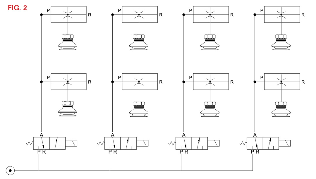
Fig. 2 is a basic schematic showing eight vacuum cups, each using a point-of-use venturi. Fig. 3 shows the same cup layout, but utilizes vacuum-control valves. The difference between these two circuits is simple: Fig. 2 uses a central compressed air supply, whereas Fig. 3 uses a common vacuum supply. The benefit of Fig. 3 over Fig. 2 is that the interconnecting lines between the vacuum venturi and the vacuum valve(s) is always fully CHARGED. (Note the direction of the arrows on the vacuum valve schematic compared with traditional pneumatic valves.) When the cups are sealed against the load being handled, the vacuum valves are turned ON, and if the distance between the valve(s) and cups(s) is short, instant grab is achieved. This volume in the tubing between the venturi and the valves vs. the valve and the cups should ideally be at a ratio of about 10:1. For example, if the tubing between the valve(s) and cup(s) is 0.03l (1 fl. oz.), and the volume between the venturi and valve(s) is 0.3l (10 fl. oz.), the following system balance would apply.
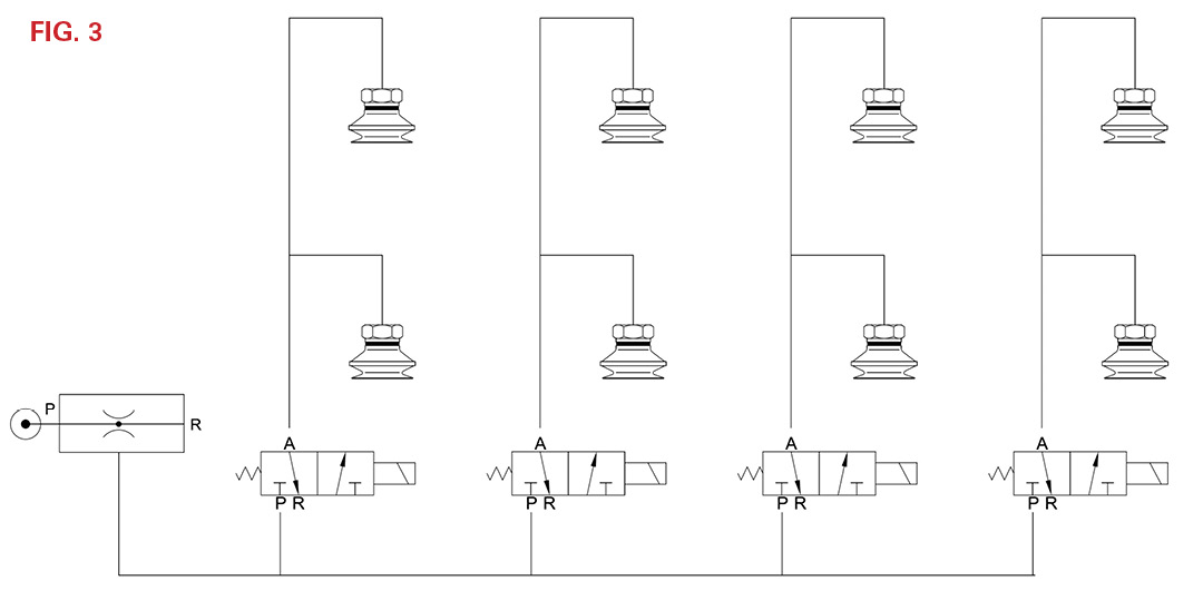
If the vacuum level is 27″Hg between the venturi/valve, when the valve opens, the complete system will balance to about 24.5″Hg (0.3/0.33 x 27) as the now-larger volume of 1.03 L (11 fl. oz.) equalizes. Therefore, the cups immediately grab to a usable vacuum level, allowing the machine to proceed in its cycle virtually instantaneously.
Compare this to the circuit in Fig. 1. No matter what venturi the machine builder has chosen, it will have a “time to evacuate a volume” value associated with it. During the initial ON time, the venturi has to get from zero to a usable vacuum level to enable the cups to grip the load being handled. The closer the venturi, the shorter this time will be. But as previously explained, this offers particular problems in filtration, oil or liquid atomization, and so on. The benefit of using the vacuum valves as shown in Fig. 3 is that proper filtration can be used between the venturi and vacuum valves without affecting cycle time. Also, the venturi can utilize an energy-saving circuit where the venturi will automatically turn OFF when it reaches a preset vacuum level. Due to the single venturi being used with suitable filtration, oil atomization will also be prevented in, for example, a steel-stamping application.
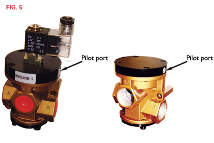
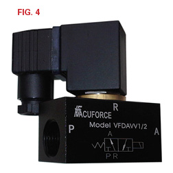 Vacuum valves are designed for use with vacuum, and pneumatic valves are designed to be used with compressed air. The valves shown in Fig. 2 can rarely be used for both. Vacuum flow requires large orifices compared with compressed air to prevent flow restriction. The valve shown in Fig. 4 is a direct-acting valve similar to the ones used in Fig. 3. These valves have very large orifices to minimize flow restriction, but because of this, they require a powerful coil of some 10 W. Other valves are available that use pneumatic power as the motive force (pilot-operated), as shown in Fig. 5. This type is also available with solenoid actuation (but pilot-assisted), utilizing a lower power coil less than 5 W in most cases but also requiring a pneumatic power-source connection.
Other types of valves are available, but 3-port, 2-position valves are all that are normally required. One condition is vacuum ON (valve open) and the other position is vacuum OFF (valve closed) with vacuum release. Many applications require fast cycle times and minimal compressed air use. Using vacuum valves, depending on the application, could be a solution for both.
This article is intended as a general guide and as with any industrial application involving machinery choice, independent professional advice should be sought to ensure correct selection and installation.
Share this information.
Related Posts


Sponsor

Sponsors