Wireless Pneumatic Solenoid Valve Interfaces
Solutions to wiring problems
By Mark Arnold, Electronic Product Sales Manager, SMC Corporation of America
Electrical connections for pneumatic solenoid valve manifolds have evolved over the years from individually wired solenoids to common cable solutions such as 25 pin D-sub connections, and then to fieldbus communications. This evolution has led to reduced installation time and reduced errors from incorrect wiring. Fieldbus communications have also enabled diagnostic feedback in addition to discrete and analog inputs common with the valve communications.
The next step in evolution is wireless communication. While there is the obvious advantage of not having to route and connect a communication cable, there are other advantages to be gained. It is not good practice to run a communication cable in parallel to high voltage power cables, as the noise induced can cause communication loss or even component damage. Not having to create a separate path/conduit for the communication cable saves money and time.
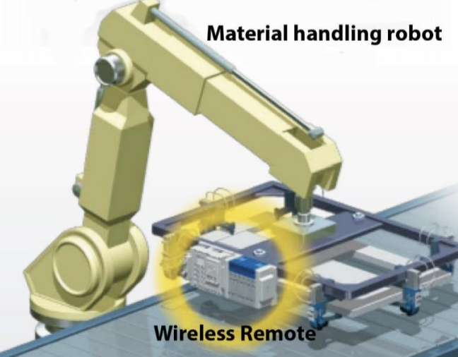
One of the largest benefits comes from tooling where the solenoid valve manifold must be moving. A common application is on the end-of-arm tooling of a robot. Routing the cable up through the robot arm has two issues. One, the pathway through the arm is often narrow and difficult to install the cable through on initial build. Two, of most concern to end users, is the tendency of the cable to fail from repeated flexing as the arm moves. This is sometimes difficult to troubleshoot the intermittent nature of communication loss. Of course, once diagnosed, the time involved in replacement is also extensive. This additional downtime is a larger burden for an end user to overcome. One may ask, if the communication is wireless, how about the power? Power still needs to be wired in a traditional method. The difference is power cables are much more flexible and robust if robotic or “hi-flex” types are specified. They do not break easily from repeated bending.
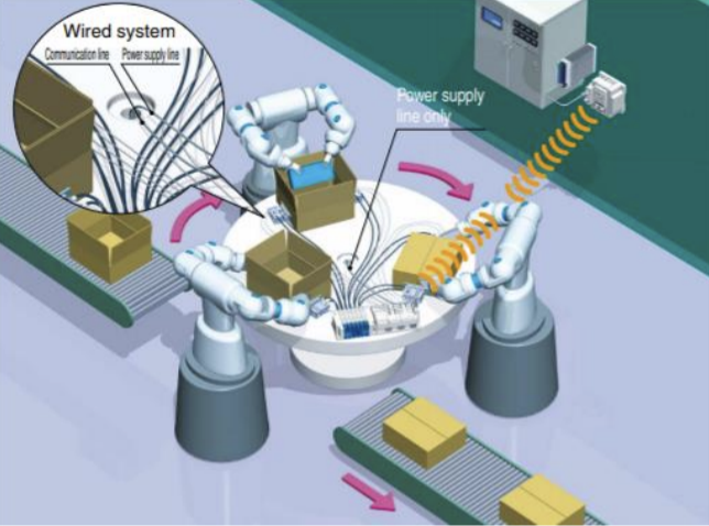
Another common application where wireless communications is advantageous is a rotary dial or turn table. To place the manifold onto the table where tubing can be shortened and reaction time of the actuators be reduced, traditionally communication and power were both routed through a slip ring. Although slip rings are reliable methods of transmitting power, quality slip rings to pass communications through are expensive and still sometimes unreliable. With the wireless valve manifold, only power needs to be supplied through the slip ring and air through a rotary union.
A third industrial application for wireless solenoid valve manifolds is tool changers. Plugging and unplugging communication connectors shortens their life, and these connections can also be a source of noise. Reducing the connection to only power and air increases the robustness of the system. There is even the possibility of using battery power to maintain the unit’s communication at all times.
SMC Corporation was approached by a customer wanting a solution to the above problems. A wireless transmission system was developed for this customer. Testing in the actual factory (automotive welding) environment proved the robustness of the system and the customer has now standardized on the EX600 wireless system for both solenoid valve control in addition to using the remote units simply for I/O.
Skepticism for new technology (especially industrial wireless) was addressed with thorough testing by SMC in labs and the customer beta test site. The architecture of the EX600 wireless system is relatively simple. Standard wired industrial Ethernet (such as Ethernet/IP and PROFINET) is connected to the base unit. The base unit can be bus connected to standard EX600 I/O modules and/or solenoid valves or even standalone. The base then communicates through SMC proprietary 2.4 GHz ISM band radio frequency transmission to remote devices up to 10 meters away. One base has enough capacity to operate 127 remote units, although the recommendation is a maximum of 15 due to bandwidth. I/O capacity for one base is 1280 inputs/1280 outputs, with each remote having up to 128 inputs/128 outputs.
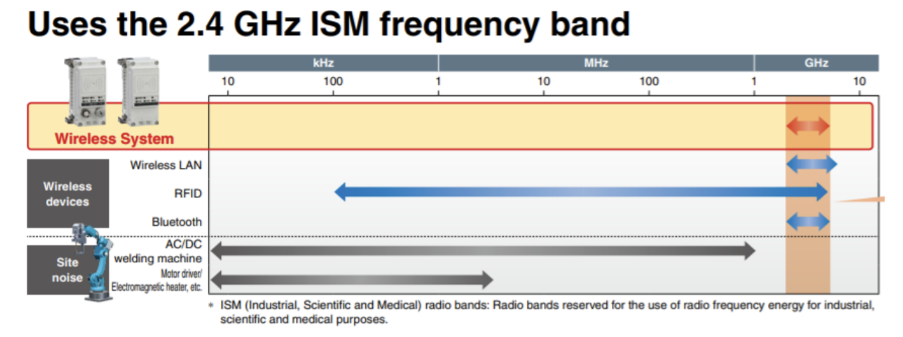
Traditionally, one of the largest concerns for wireless systems in an industrial system is reliability and resistance to electromagnetic noise. Operating at 2.4 GHz places the frequency above most common industrial noise such as AC and DC welding, motor starters, heater contacts, and so on. For Bluetooth, wireless LAN and some RFID devices, 2.4 GHz is used. To avoid potential interference, SMC uses 79 channel frequency hopping around the 2.4 GHz range. The channel is changed automatically every 5ms to prevent being interfered with or interfering with another device. If for some reason there is interference, or the signal is blocked by a large ferrous object, the units continue to retry communication automatically. If the number of retries exceed 31, an alarm bit can be set. Once whatever interference is removed, the unit automatically reestablishes communication.
A question could be asked: Why not use 5.8 GHz instead, where there is even less chance of interference with the more common 2.4 GHz frequency devices? One of the differences is range. The 2.4 GHz signal will travel further at the same power rating. It is also better at diffracting around solids. Even so, we do recommend trying to maintain line of sight as much as possible. This involves putting the base in a centralized location, usually higher up in the machine for best visibility. Another reason that 5.8 GHz frequency is not used is that some countries require the end user to have a license to operate 5.8 GHz equipment.
Security is another concern. IT departments tend to worry when an unknown wireless network is brought into their facility. These factors should reduce that concern:
- The system is encrypted between the base and remote.
- Because of unique pairing between the base and remote, they ignore all other signals.
- The communication used is not wireless LAN or Bluetooth, so devices listening for those type signals will not see the SMC network.
- The frequency hopping occurs every 5ms, so locking on to one frequency is more difficult.
- Because the signal range is limited to 10 m, someone “listening in” from outside the facility would likely not be able to listen in to the network traffic. A very powerful transmitter would have to be used to influence a base or remote even if it could be determined how to communicate with.
- Most industrial control systems have a firewall of some sort between the PLC and any PC-based information.
- It would be much easier to steal or disrupt data from inside the facility than outside.
No system is 100% safe, but hacking or disruption would not be an easy accomplishment for someone with malicious intent.
Share this information.
Related Posts


Sponsor

Sponsors