Bringing Reliability to High-Pressure Hydraulic Cylinders
By Ed Danzer, 6K Products
As hydraulic system working pressures increase, component design details become more important.
High system pressure, defined as 6,000 psi (41,000 kPa or 410 bar), is the pressure setting on some newer excavator functions. A system that operates at 6,000 psi will see short pressure spikes that are two to three times the working pressure. This means the components need to handle 12,000 to 18,000 psi (82,737 to 124,105 kPa or 827 to 1,241 bar) pressure spikes for a reasonable service life of 8,000 hours, or four years, and should not fail in less than 2,000 hours, or one year of service.
Cylinder design considerations
When a machine or attachment is being designed, the designer has an idea of what the unit should do and how it should be done. As soon as you hand the machine to a different operator, the application, duty cycle, and operating parameters have changed. In some cases the change is enough that things start to fail. Frequently, the cylinder will be subjected to a work-induced load that is much greater than what is possible by direct control.
Both counterbalance valves and pilot-operated check valves are used to hold a cylinder in position, and both valves can produce additional loads on the cylinder components when in operation. Some load-holding valve settings are increased by back pressure on the pilot port.
A short-stroke cylinder does not typically need to be concerned with buckling load design. A long-stroke cylinder will require running a buckling load calculation. Use standard NFPA/T3.6.37 R1-2010 for buckling calculations.
The speed the cylinder will move, or the flow going into the cylinder, must be considered to determine port and plumbing size. This speed is also important when designing cushions if they are required.
Choosing the correct bore and rod size can be the single most difficult aspect of the cylinder to determine because of the forces required when extending and retracting, the stroke required, and the pin centers distance needed to be met. If the cylinder needs cushioning, this could change the bore or rod size requirements. Sometimes a larger bore and rod will be required to meet all the design needs. One side of the piston may need to run at a lower pressure to meet the force requirements as well as structural requirements, such as the piston-to-rod interface, the piston fastening needs, and buckling of the rod.
It may be difficult to determine the load, or load vectors, for a highly accurate model, but it is important to determine this data if you expect to create a robust design. Some designs will require enough mounting flexibility that either adequate side clearance, self-alignment capabilities, or both need to be incorporated into the anchor and pin-joint design. If possible, do a finite element analysis of the structure to determine its deflection.
Pin-joint design needs to be applied to both the cylinder ends and the pin anchors being actuated by the cylinder. For boom pivot joints you will need to look at not only the loads created by the cylinder, but also by other loads of the system such as torsion loading. For cylinder pins, you need to design for the maximum load the cylinder will see, which may be the work-induced loads. We use 6,000 psi projected area loading on the bushing or bushings. We recommend using a bushing length that is about two times longer than the pin diameter if possible. The fixed pin-holes widths should be .75 to 1.25 times the pin diameter. Longer, smaller diameter pins and bushings tend to bend more than shorter, larger diameter pins and will make the manufacturing and maintenance more expensive over the life of the cylinder.
For many applications, slowing the cylinder at the end of stroke is not required. If the application has high inertia loads and no speed control feedback, building deceleration cushions into the cylinder can be an inexpensive solution. Designing an adequate cushion will require a good understanding of the application and loads to be controlled. To cushion a cylinder there has to be a way to meter the oil going out of the cylinder. There are several methods of metering the oil flow and controlling cushion pressure. We typically use the piston to close the port to increase the area decelerating the load. The pressure on the side of the piston opposite to the side being cushioned is additive to the mass being decelerated and must be considered during design.
Common failures
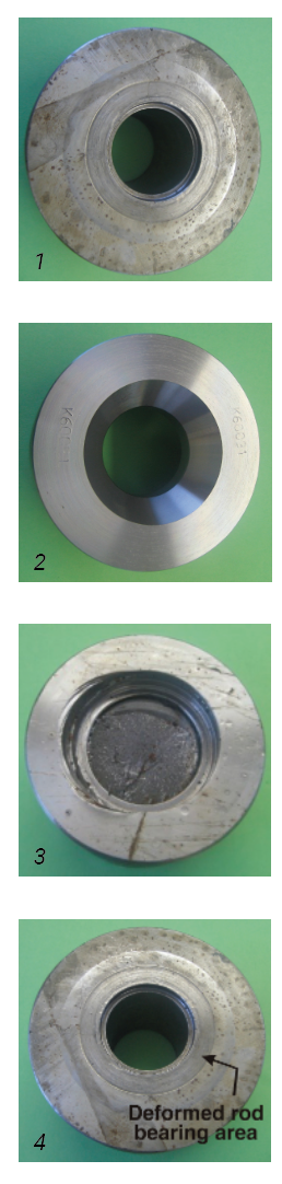 Piston-to-rod interface is one area of high-pressure cylinder design that seems to be the most difficult to manage well. Many times the bore and rod size are chosen from a prior lower-pressure design. This can get the designer into trouble if the fastener is too small, or if the piston-to-rod interface area is too small. Figures 1, 2, and 3 are all 5-inch bore by 3-inch long rod, log-grapple cylinder piston designs.
Figure 1 is the 5K design I developed in 1985. It uses a 1½-inch NF nut to hold the piston in place. Figure 2 is my 6K design, developed in the late 1990s, with a 1¾-inch NF nut. Figure 3 is a competitive design, developed in the early 2000s, with a threaded-on piston.
This cylinder is a shorter-stroke cylinder that does not have extreme side load, but it does have a pilot-operated check valve hard plumbed to the barrel, so if a hose fails the cylinder cannot drop the load. There will be times when the operator will hit the grapple in such a way that the cylinder will see high extension forces acting against the threads. Sometimes the operators will use the grapple to pull stumps so the blind end of the cylinder will see pressures up to about 20,000 psi before there is a catastrophic failure. The 5K piston design did not have a large enough thread, allowing the rod to break at the end of the threads. Also, the rod-bearing area was not large enough so the piston would cold form over the rod.
Figure 4 shows the area that was cold forming over the rod on a 5K cylinder. When the rod and piston bearing area are loaded above the yield point of the material, there will be material movement, and this will allow the piston to come loose causing further damage.
In figure 3 the internal thread piston has an even smaller rod-bearing area. There must be clearance in the thread for assembly. This clearance, and the clamping force of tightening the piston, will allow the piston to cold form over the rod even sooner than other designs. The deflection in the threads when the piston loosens can cause breakage in the rod, as shown. The 6K piston in figure 2 has the larger fastener, and to get a larger bearing area a tapered interface is used. We have upgraded the piston to 4150 HT on the 6K design for additional protection from pressure spikes. We have customers that have used all three cylinder designs and have never had a 6K piston-to-rod interface failure. The limitations of the current 6K design are at about 18,000 psi when the barrel will yield, or the pilot-operated check valve will fail.
Material choice
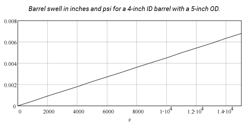
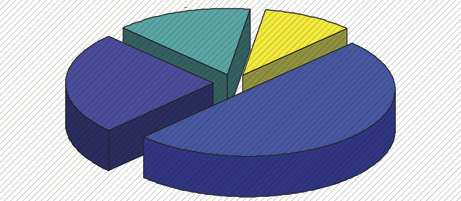
With the highly concentrated force on the rod and piston, the materials used for the rod and piston should have a similar hardness, a high-impact capability, and may require a high Charpy impact value at low temperatures. This is required if the cylinder is being used at low temperatures. The barrel should be made from a material with a high-yield strength, good weldability, and adequate impact capabilities. Do not use materials that contain free-machining elements in parts that will be welded. These free-machining elements include, sulfur, lead, manganese, calcium, selenium, tellurium, and bismuth. The wall thickness choice should be thick enough to keep barrel swell low to reduce seal failure. The graph shows barrel swell in inches and psi for a 4-inch ID barrel with a 5-inch OD.
Barrel swell can reduce seal life by increasing the gap between the piston and barrel. This increases the diameter of the element or elements contacting the barrel, causing an increased seal-groove volume.
There are many different methods to attach the head gland to the barrel. The most reliable design will handle the maximum load the cylinder sees when extended by pressure in the blind end, plus the stopping load. If the cylinder has an extension hard stop, then the stopping load is 0. If the cylinder has to stop the movement of the structure it is driving, it must be calculated and added to the extend force. In the case of excavator boom and bucket cylinders, this can be a large force. I do not recommend screwing the head into the barrel.
As the pressure swells the barrel, it increases the thread clearance, which allows movement that will cause thread wear and reduce the service life of the cylinder. Barrel or gland nuts work if properly sized for wall thickness. It also helps to use Acme or square threads. Buttress threads have a sharp, thin cross section, so they can be weaker than other thread forms. Using a ring of cap screws is a common method that works well if properly designed. The thickness of the flange that the fasteners clamp must be thick enough to not deflect during loading. The 5K-cylinder design had flanges that were marginally thick enough, so in an application where there were high forces at the end of the cylinder travel, the deflection caused the head and cap screws to fail sooner than in other applications. Using a flange that is twice as thick as the bolt diameter will usually be adequate for most applications.
Welding failures are common in high-pressure hydraulic cylinders for many reasons. Let’s look at the more common ones and some repair information.
Weld chamfer. The weld chamfer needs to allow for correct wire stick out and shield gas control, but no larger than necessary as this will increase welding time and weld generated distortion.
Filler material. Early in the development of high-pressure cylinders, one of the weld failures came from using the incorrect yield strength filler materials. Most tubing for high-pressure cylinders will need a yield strength greater than 70,000 psi. This will require a filler material that is 80,000 psi yield or higher. E80 wire is typically a good choice.
Weld bead size. To ensure the weld does not have too much stress from welding, I recommend using a multipass pulsed-spray weld procedure. This will also reduce distortion of the parts. There should be a small contact area where the barrel tube and the blind end connect, so if the barrel needs to be replaced, the barrel pilot and locating shoulder machined on the blind end will still exist after weld removal. This does require the weld to be larger in diameter than the barrel, which may not work in some applications.
Weld repair. Weld repair in hydraulic cylinders can be a challenge because of oil saturation. Low-hydrogen welding materials will not seal oil-contaminated metals. The first pass should be done with a 6010 or 6011 stick rod using a whipping motion. Cover passes using higher-strength filler materials are required for structural integrity.
The materials chosen for sealing and guiding the rod and piston can be the single most difficult portion of high-pressure cylinder design. Many designs are based on using existing seals that work acceptably in lower-pressure applications. Some designs use low-cost products, so repairs are less expensive. For the end user, in most cases, the cost of downtime far exceeds the cost of a properly designed and installed seal kit.
Every cylinder needs to have guide bearings in the form of wear rings or plain bearings. This is to guide the rod in the head gland and the piston in the barrel. These guiding components will have to accept the side load the cylinder sees, hold the running clearance, and must be included in the repair seal kit.
Finally, the seal kit should include all the parts to make the cylinder like new.
Do not use pipe threads for anything operating over 100 psi if possible. Do not weld on commercial hydraulic adaptors, as they are manufactured from free-machining steels and will crack near or in the weld area.
Try to not have right- and left-handed cylinders. Determining the correct hand can be difficult for the customer and will increase the cost of inventory of spare parts.
Use thicker wall tubing, or pipe, when there is the possibility of being hit during operation. If the tubes need to be removed and if it’s possible, have some part of the tube attachment system welded to the barrel. Clamps will come loose from pressure expansion of the barrel and can allow the tube to rotate enough that the tube, hose, or cylinder barrel will be damaged.
High-Pressure sealing challenges
Pressure and velocity (P/V) capability of the sealing material is an important consideration in high-pressure sealing. When the piston and rod assembly are moving, the seal surface becomes a bearing that has no running clearance and must run almost dry to stop fluid bypass. Every sealing material will have a different P/V value relative to different contacting materials. Most published P/V values are not correct for sealing applications, and correct P/V information may not exist.
If there is too much space for movement in the seal groove, it can reduce seal life. Filled seal materials tend to break down under high pressure, scratch components, and contaminate the hydraulic oil. Glass-filled material tends to be brittle where the glass bonds to the parent material and will deposit glass into the hydraulic system as they fail.
Off-highway equipment cylinders can see high pressure spikes during operation that will reduce seal life. Proper use of step-cut or lap-cut wear rings, zero-split clearance bushings, or wear rings can be a better solution than buffer seals. Buffer seals can trap high-pressure oil against the rod seal, causing premature rod-seal failure. A backup ring behind the rod seal to reduce extrusion is a good option for all cylinders.
Effects of temperature on seal performance
We have found that most elastomers have increased compression set when cooled below freezing and raised to operating temperature daily. Many O-ring grooves do not have dimensions to allow for the cyclic temperature compression set. If you see O-rings damp enough to collect dust in static applications, this leak is probably from cyclic temperature compression set.
Elastomers have a higher coefficient of thermal expansion than steel. This means the seal will shrink more when cold than steel does and expand more when hot. When looking at seal groove dimensions, it is important to consider the size the elastomer will be during the lowest and highest operating temperatures. Too little or too much volume can reduce seal life.
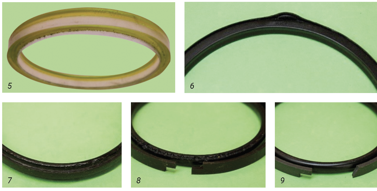
Extrusion, nibbling, and breakage are common failures. Figure 5 is an example of extrusion in less than 300 hours of operation from too much pressure for a urethane seal. Figure 6 is seal extrusion from honing a cylinder to clean it up during repair without increasing the diameter of the piston. Figures 7 and 8 are examples of nibbling. Nibbling can be caused by barrel swell, axial movement of the seal in the groove, or incorrect groove dimensions. Figure 9 is an example of a filled material breaking, and the sides of the expander show evidence of axial movement in the groove.
When assembling hydraulic components, use oils or greases that are compatible with the hydraulic oil used in the machine. Do not use materials that contain mineral-based additives or thickeners. We use a polyurea-based grease to meet these requirements.
If you are faced with the task of redesigning a cylinder to handle higher working pressures, use finite element analysis or other simulation tools to reverse engineer failed components and to qualify new designs. Remember that just because component design, material choice, seal choice, or assembly method worked at 5,000 psi does not guarantee it will perform well at 6,000 psi.
Share this information.
Related Posts
Lower the Pressure to Keep Your Compressed Air System Healthy

Back to the Future at IFPE: Are We There Yet?
Burr Identification and Removal

Wandfluh Launches New Modular Product Series
Motion Control of a Single Actuator Against a Resistive Load

Offshore Technology Conference Sees Record Number of Attendees in 2013
2 thoughts on “Bringing Reliability to High-Pressure Hydraulic Cylinders”
Leave a Reply
Sponsor

Sponsors
I didn’t know that welding failures are common in high-pressure hydraulic cylinders. I want to learn more about hydraulic pistons for a project I want to start. I’ll look on other websites too to see if there is something more I need to know about the welding failures.
Where can I learn from to design a 8¨internal diameter cylinder for 40,000 psi?