Clamp and Drill Circuit Will Not Release the Part
A new hydraulic system was installed on an old “Clamp and Drill” machine. A PLC would shift a directional valve clamping the part and a proximity switch would then signal the PLC to advance the air operated drill. At the same time, the clamp directional valve would center, trapping the clamp pressure. When talking to the maintenance man and operator, they said that when they started up the new installation, the electrical controls engineer had the cylinder retracting when it should be extending. When they contacted the engineer, he told them to switch the cylinder hoses and everything should be OK.
After switching the hoses, they found that the pressure reducing valve would only work on the rod side and allow the cap end to build to system pressure, causing damage to the clamped part.
The engineer was told of the new problem, so he switched the wiring to the solenoids and also returned the hoses to their original positions. This now allowed reduced pressure of the cap end and allowed the cylinder to extend when it was signaled to extend.
A different problem developed. The reduced pressure on the cap end of the cylinder, after about 15 seconds, would start to slowly creep up to system pressure.
Any idea what is causing the new problem?
See the Solution
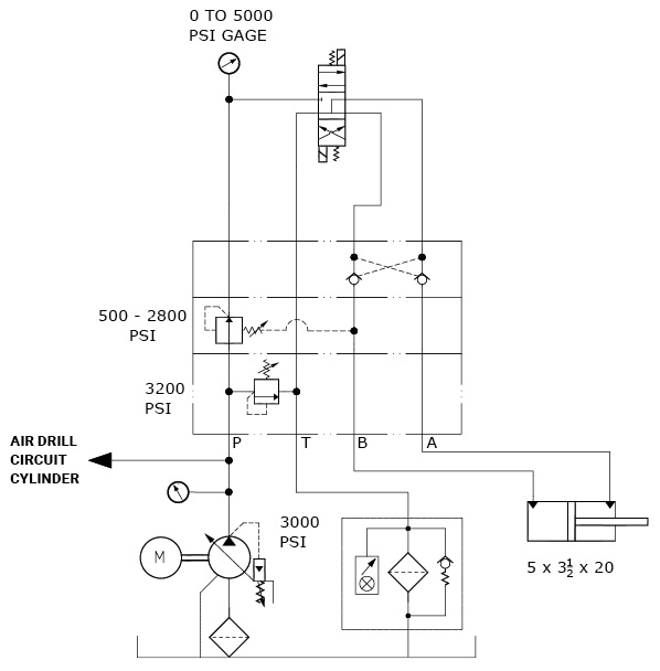
This problem represents a common situation we are faced with probably 30% of the time. The circuit shown was given to us as the existing schematic. What they did not tell us was that the “A and B” hoses were returned to their original position when the engineer switched the coil signals.
We kept telling them there was something wrong and that the circuit as shown would not reduce the cap end pressure.
Now that we had the correct circuit, we were able to determine that the pressure reducing valve needs to be mounted above the pilot operated checks. The drain line was pressurizing the rod side, causing both pressure build up on the rod side that intensified the cap end pressure, and causing the reducing valve setting to increase.
Switching the two module positions fixed the problem.
By Robert Sheaf, CFPAI/AJPP, CFPE, CFPS, CFPECS, CFPMT, CFPMIP, CFPMMH, CFPMIH, CFPMM, CFC Industrial Training
Share this information.
Related Posts
3 thoughts on “Clamp and Drill Circuit Will Not Release the Part”
Leave a Reply
Sponsor

Sponsors
The drain line for the PRV is plumbed into the ‘B’ line between the cylinder and PO check, allowing full system pressure to bleed through in the cap end of the cylinder. Quick fix would be to swap the PRV sandwich block with the PO check block, but the proper way would be to order a sandwich block that drains to tank for the PRV.
The cap end cylinder pressure is increasing due to spool leakage from the reducing valve. Having the reducing valve spring referenced to a load holding port is not a good idea, especially with a pressure compensated pump. If you change the arrangement of the sub-plate valve stacks by placing the reducing valve section closest to the directional valve and the po check section in the middle, the reducing valve will be vented through the center spool condition, and the system will function as intended.
Externally during the spring chamber on the pressure reducing valve.