Come Together: Hose-Coupling Interfaces
By Matt Petti, Director of Global Product Line Management, Gates Corporation
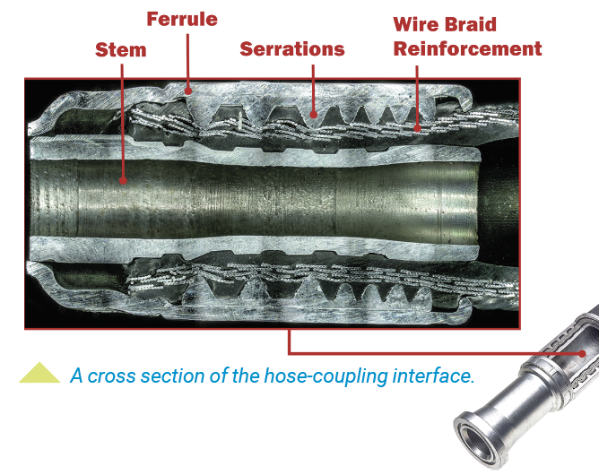
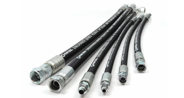
Hydraulic hose assemblies are an integral part of a hydraulic system, withstanding thousands of psi of fluid pressure, powering the articulating arms of mobile construction equipment, the hydraulic ram of a 100-ton hydraulic press, and many other heavy-duty applications. The construction of a typical hydraulic hose assembly is relatively simple – a section of rubber hose with metal couplings crimped onto both ends. What is often overlooked is the interaction between the hose and the coupling after being crimped together, referred to as the hose-coupling interface. This carefully balanced combination of a metal ferrule, rubber hose, and coupling stem (also known as a hose insert) gives a hose assembly its overall pressure rating.
Both the hose and the couplings are designed for use at a certain working pressure, so it might be assumed that when combined, the assembly’s pressure rating would match the lesser rating of the two components. But the hose-coupling interface, a critical portion of a hose assembly, can often be the limiting factor when determining a complete assembly’s working pressure. To develop a dependable assembly working pressure and potential working life, there are several steps to the process. Choosing the correct ferrule, building a crimping profile and range, testing complete assemblies, including specific crimper settings, and recognizing sources of failure are all involved in the process of designing a reliable hose assembly.
To design couplings with a robust hose-coupling interface, there are variables such as the specific hose cover material, tube material, reinforcement layer thickness, and reinforcement ductility. When the ferrule component of a coupling is designed, these factors are taken into consideration and often affect the number and depth of the serrations lining the internal circumference of the ferrule. Many manufacturers of couplings intend for these serrations to penetrate the hose’s cover material and embed themselves in its reinforcement layer, creating a stronger bond with the hose when crimped. Gates calls this a “bite-the-wire” coupling. Also, in a proper crimp, the rubber of the hose flows between the serrations as it is being crimped, further improving the connection’s strength while minimizing intrusion from external elements. This is why ferrule design is closely tied to the type of hose, with some coupling families offering multiple types of ferrules, depending on the hose or application.
The first step in qualifying a coupling with a hose is identifying the correct ferrule to pair with the hose. For example, even if the hose inner diameter (ID) is known, it’s possible a different ferrule will be required for an SAE 100R1 hose versus a 100R2 hose because of the differences in hose outside diameter (OD). One-piece couplings come with a ferrule already attached, so the ferrule sizing is considered when choosing the complete coupling.
Once the correct coupling components are chosen to be qualified with a specific hose, the next step in qualification is to develop a manufacturer-provided crimp specification. This specification often refers to the final crimped OD of the coupling ferrule after it has been attached to a specific hose, measured using calipers on the flat portions across the ferrule diameter. To develop these crimp specifications, coupling development engineers estimate a target crimp OD using historical data and material property calculations. Engineers perform initial crimps using a hydraulic crimper, with a little trial and error to get to the target crimp OD. During crimping, due to the pressure exerted by the compression of the ferrule and rubber hose, engineers expect that the coupling stem has a certain amount of bore collapse. Using pin gauges or bore gauges (depending on the inner diameter), they take measurements to determine if there is too little collapse, resulting in a weaker clamping force between the ferrule and stem, potentially leading to coupling blowoff when pressurized. Too much collapse constricts the fluid pathway and decreases overall hydraulic system efficiency, in addition to potentially weakening the strength of the stem and leading to premature failure. Using the gauges, engineers compare the measured bore to the minimum bore allowed by SAE J516. They check the concentricity of the crimps and look for uniform crimping results around the circumference. They repeat subsequent crimping trials until they achieve an acceptable bore collapse, recording the crimp OD of the successful crimp result, which will then become the starting crimp OD for performance testing of that coupling-and-hose combination.
Testing
After determining a starting crimp OD, the real fun begins. The next step in the qualification process is testing the hose assembly under pressure, running it through several tests specified by industry standards like SAE J517 and J343 to determine the assembly’s integrity. Some of these tests are to ensure customer safety, using test parameters that allow for a sufficient safety factor to accommodate spikes in system pressure when in use in the field. Other tests in SAE J517 check the assembly’s performance in simulated use, testing for things like hose dimension changes, hose degradation from external sources, and potential life of assemblies.
A few tests stipulated by SAE J517 are pertinent to the hose-coupling interface: the proof test, burst test, leakage test, and finally, the impulse test. Proof testing a hose assembly is a simple test that ensures the assembly is capable of holding pressure, requiring a hydrostatic pressure of twice the working pressure, held for 30-60 seconds, and checked for leaks at the coupling and along the hose length. After passing proof testing, select assemblies are tested for burst and leakage, putting the assemblies into extreme pressure conditions to see how they perform. Burst testing requires taking the assembly to a minimum of four times the working pressure, often higher, until the assembly has catastrophic failure. Leakage testing similarly pushes the assembly to its performance limits, bringing the pressure to 70% of the minimum burst pressure, held for five minutes, removing pressure, then repressurizing to 70% of minimum burst. After advancing through this pressure cycle, engineers check the assembly for leaks or signs of failure. All three tests have binary results, either pass or fail.
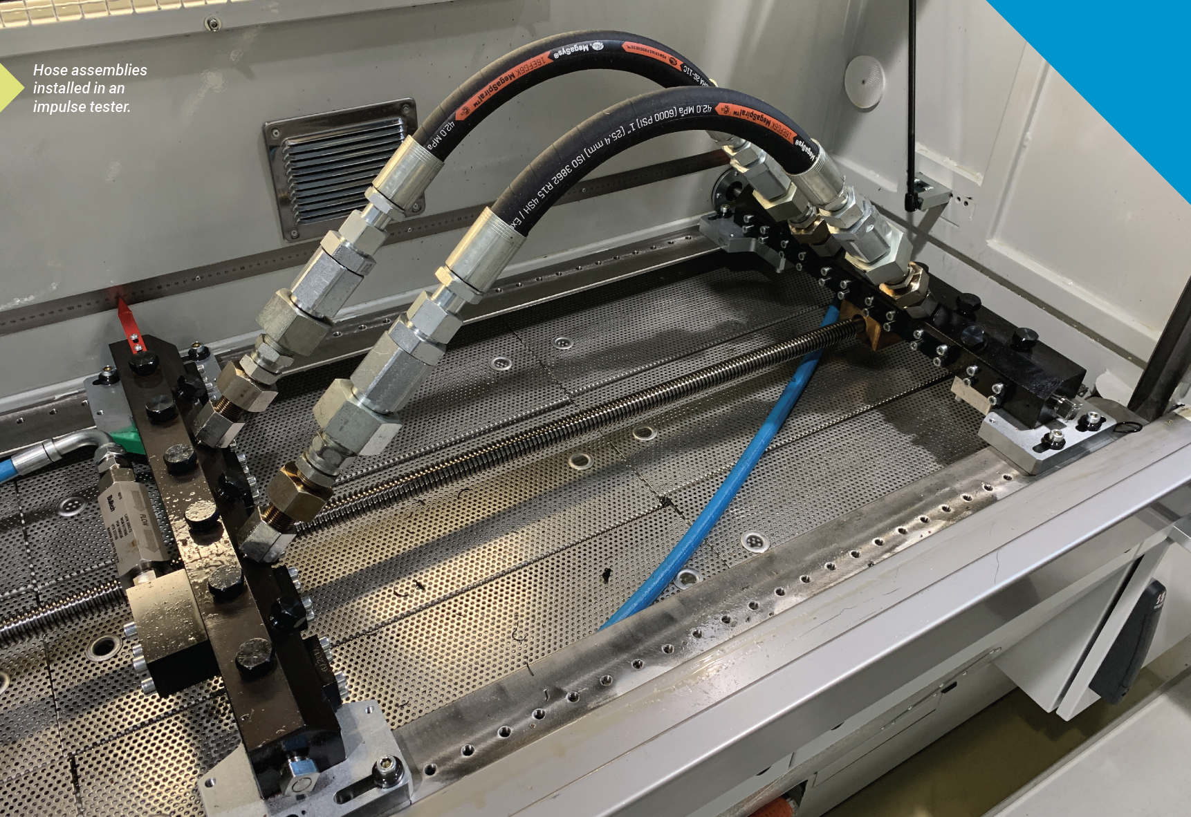
The last test for hose-coupling interface evaluation is impulse testing. While impulse testing can have a binary result of whether it passes industry standard minimum impulse cycles, it is often run beyond industry minimums to test how long the hose assembly could potentially last in high-impulse cycle applications. The hose assembly, made to the proper length to allow the rated minimum bend radius, is attached to the manifold inside of an impulse tester, and the assembly is subjected to a repetitive pulsation of temperature-controlled hydraulic fluid through the hose at a frequency specified by SAE J343. This cycling of pressure mimics the pressure changes in a hydraulic system of a customer’s machine, although at an accelerated rate. This allows the hose performance to be evaluated in a number of days in a laboratory environment as opposed to weeks or months of field testing.
During impulse testing, engineers use a range of crimp ODs above and below the starting crimp OD across several hose samples, recording the number of cycles each sample achieves before failure. When testing over a crimp range, they expect “edge failures,” where the ends are over-crimped or under-crimped, reinforcing the results of the crimp OD study. When they compile the data, they determine an optimum crimp OD using a statistical analysis of the best performing samples. The crimp OD they discover through this process becomes the specified crimp OD for use by hose assemblers.
Providing settings
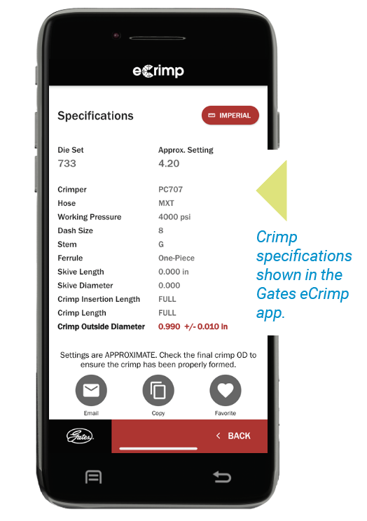
The last step for a manufacturer who offers crimpers in their product line is to make the crimping process easier for their customers by providing crimper-specific settings to reach the specified crimp OD. For example, Gates publishes crimp specifications for its hose-coupling combinations with crimpers and dies in a printed manual as well as on their eCrimp website and mobile app. While some high-volume production-grade crimpers can program a specified crimp OD into their user interface, many crimpers do not have a direct method to tie machine settings to crimp OD. When there are a variety of crimper models and die sets available, it can be an arduous task to develop crimp settings for each hose size, coupling type, die set, and crimper model. The process often begins by loading the correct die set into a crimper, determined by the closure for that specific die set. Using historical machine settings with the specific die set, engineers adjust the crimper to an estimated setting that should achieve the specified crimp OD. A series of crimp trials narrows the machine settings to hit a crimp OD within a specific tolerance above and below the specified crimp OD. The allowable tolerance varies from manufacturer to manufacturer. Engineers repeat this process for each available crimper model and record machine settings for assemblers to quickly dial in crimps during assembly production.
The effort that goes into qualifying hydraulic hose-coupling combinations ensures a reliable, high-quality hose assembly that meets performance expectations while maintaining customer safety as the highest priority. When a scientific, repeatable qualification process isn’t performed to verify a hose-coupling combination, the consequences can range from inconvenient leaking to catastrophic failure. We can attribute some failures in hose assemblies to the hose, as with a pinhole burst or poor wire-reinforcement construction. We can attribute other failures to the application, such as an over-tight bend radius or a bend near the coupling that puts increased strain on the hose-coupling interface. There are also failures specific to coupling design, such as leakage of hydraulic fluid at the termination or mechanical failure of coupling components from over-torquing the termination.
Interface failures
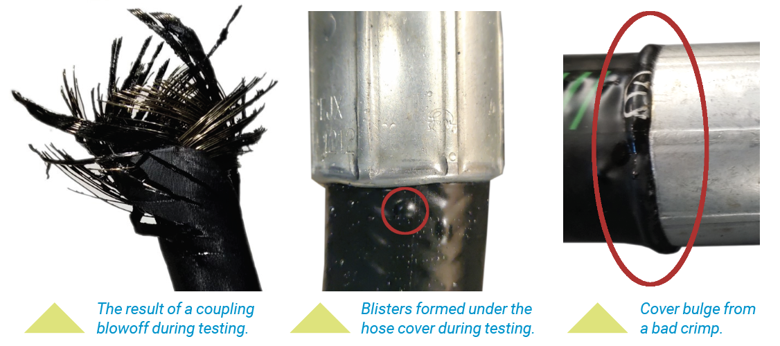
Failures at the hose-coupling interface are a focus during the qualification process and can differ from the failures attributed to individual components, resulting instead from the combination of the hose and coupling. A common failure is a visible drip of hydraulic fluid exiting the coupling ferrule where it meets the hose, often resulting from a nonconcentric crimp or improper die closure. While rubber is an ideal material for hydraulic hoses because of its flexibility and durability, the integrity of the rubber in the hose-coupling interface area can degrade over time, particularly when exposed to high-temperature hydraulic fluid for hundreds of thousands (even millions!) of impulse cycles, which can also cause weeping of fluid at the hose-coupling interface over time. A more difficult failure to diagnose is a leak caused by poor crimping in which the hydraulic fluid escapes the hose-coupling interface between the hose’s tube and cover layer, travelling down the reinforcement wire or fiber until it creates a blister in the hose cover or creates a pinhole leak. The most severe failure at the hose-coupling interface is called coupling blowoff. This often occurs from a crimp with insufficient compression and bore collapse, resulting in a loose connection of the coupling to the hose. While the crimp may appear to be satisfactory at initial pressurization, as the assembly is submitted to hundreds of thousands of impulse cycles by the hydraulic pump, the coupling in a loose crimp can separate from the hose at extremely high speeds, spraying hydraulic fluid in the process, creating a very dangerous scenario. Causes for these hose-coupling interface failures in the field are often found during lab testing, further reinforcing the importance of the qualification process.
When couplings and hoses are specifically designed to be compatible with each other, it greatly increases the chance of creating a high-quality, long-lasting, safe hose assembly. Completing a thorough, scientific qualification process further guarantees not only the compatibility of the hose and coupling but empowers the various parties responsible for crimping hose assemblies with the necessary guidance to create repeatable, reliable crimped assemblies. Ensuring that the coupling and hose are from the same manufacturer and that crimp specifications exist for the combination from that manufacturer improves performance and reliability. The risk assumed by combining couplings and hoses that have not been qualified by their manufacturers is significant, as the possibility of failure dramatically increases and can be severe.
Share this information.
Related Posts

Sponsor

Sponsors