Test Your Skills: The Function of a Prime Mover
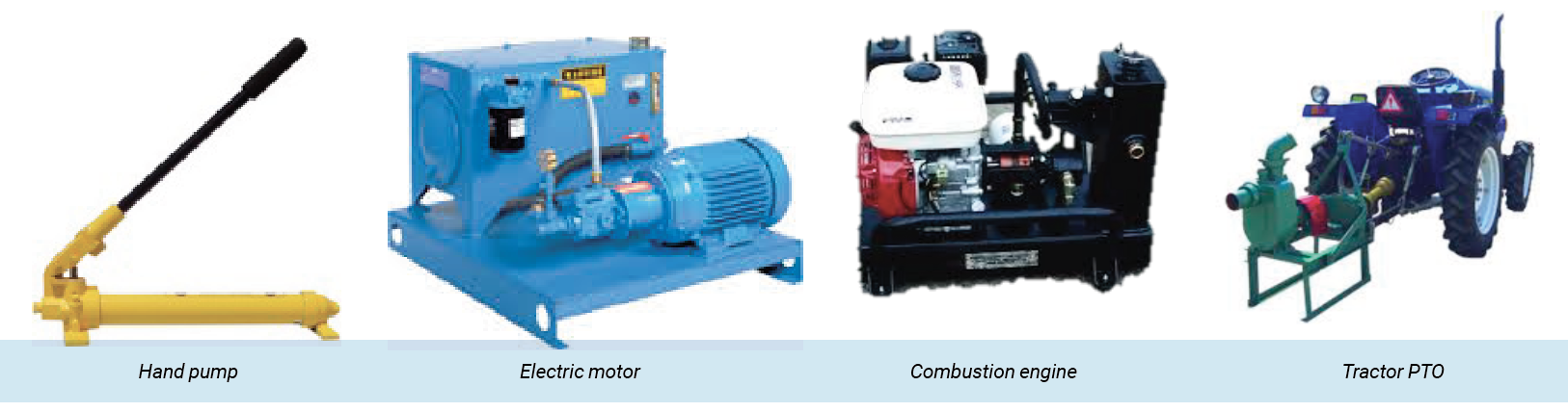
A complete hydraulic system must include an initial energy source. This energy source is referred to as the prime mover, and it must be considered when maintaining or repairing any hydraulic system. The prime mover could be as simple as a manually operated lever on a jack where the input energy is human effort, or it could be a massive diesel engine on earth-moving equipment or on a merchant marine vessel. In either case, there must be energy entering the system to push the fluid doing work. In mobile equipment, the prime mover is often an internal combustion engine. Hydraulic pumps are connected to the engines and convert the mechanical energy at the crank shaft to hydraulic energy.
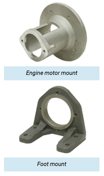
Methods for connecting a pump to an internal combustion engine vary with each application, but there are some common considerations. The pump shaft and the shaft to which it is connected must be properly aligned to prevent damage. With smaller engines, there are mounting adapters where one side is bolted directly onto the engine face and the other side is machined to accept the pump with an appropriate flexible coupling. These are designed to keep the shafts properly aligned.
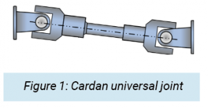
If a pump mount is not available, a foot mount can be used with a flexible coupling or a drive shaft. If a drive shaft is used, it is critical that the shaft on the prime mover and the shaft on the pump be properly aligned. A drive shaft uses a set of Cardan universal joints (figure 1) to couple and align the shaft of the prime mover with the shaft of the pump. The yokes of the Cardan joints must be in phase and the drive and driven shafts must be parallel to prevent vibration.
Sometimes the drive shaft is connected directly to the harmonic balancer on the vehicle engine through a modified radiator. The angle of the drive shaft from the pump to the harmonic balancer needs to be considered. The maximum angle varies with the engine rpm.
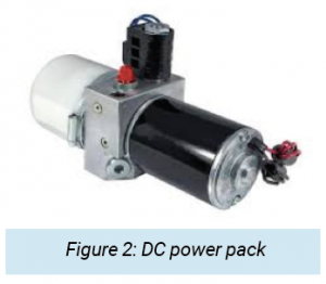
 Electric motors are the prime movers in many mobile hydraulic applications. Smaller systems use direct current (DC) motor-driven power packs (figure 2) that are powered off the vehicle electric system. This provides the advantage of on-demand power, using the energy stored in the vehicle’s battery. The engine may be turned off while the hydraulics are being used, saving energy and making for a quieter environment. In this case the small hydraulic pump is directly coupled to the electric motor. A manifold holds some directional and relief functions along with porting and connection to the attached reservoir.
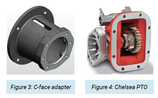
 Larger electric motors are used, especially in marine applications, where alternating current is available from generators. Mounting pumps to electric motors requires the same concerns about alignment as with internal combustion engines. Electric motors that have the correct bolt pattern can be equipped with a C-face adapter (figure 3), which is made to properly couple and align a hydraulic pump. The C-face adapter bolts directly to the motor and the pump is then mounted on the adapter. The adapter is machined to accept and properly align a pump with a matching flange face.
If a C-face motor and adapter are not available or there are other physical constraints, a foot mount adapter can be used. It is critical that the shafts of the pump and motor are properly aligned.
Gearboxes
When the prime mover is an internal combustion engine that is the power source for the entire vehicle, the hydraulic system may be an auxiliary function and will be connected to the prime mover through a power take-off (PTO) attached to the vehicle transmission. The PTO is a gearbox (figure 4) in which the shaft speed (rpm) may be different than the engine rpm. The power potential of the PTO is dependent on its gear ratio and the torque rating of the shaft.
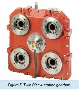
An internal combustion engine may be the prime mover for a number of hydraulic systems and so may use a multistation gearbox (figure 5).
 Both internal combustion engines and electric motors may require some type of gearbox. The power transmitted by a hydraulic pump is a product of both the flow rate and the pressure. The power delivered by the prime mover is determined by the rotational force (torque) available and the rpm. If the output of the prime mover does not match the requirements of the hydraulic system, a gearbox can reduce the speed and increase the torque, or it could increase the speed and decrease the torque.
All gearboxes, whether used to increase or decrease speed, have some degree of mechanical inefficiency. This inefficiency will consume some of the power from the prime mover and must be understood when gearing is used.
For example, a hydraulic system requires 45 lpm at 10 MPa (12 gpm at 1,450 psi). The hydraulic system operates at 85% overall efficiency requiring about 9 kW (12 hp). The truck engine can easily supply this much power at 900 rpm. However, the pump requires 1,800 rpm to supply the flow. Raising the engine rpm to 1,800 would provide the necessary flow but would waste a lot of energy. By using a PTO with a step up gear ratio of 2:1, the engine can run at 900 rpm while the PTO shaft would drive the pump at 1,800 rpm. If the PTO has a mechanical efficiency of 90%, the power draw from the engine would have to increase to 10 kW (13 hp).
Test Your Skills
1. When using a foot mount to connect a prime mover to a pump:
a. Alignment is necessary.
b. Alignment becomes unnecessary.
c. Any extra torque is absorbed by the hold down bolts.
d. A four-bolt mounting pattern is required.
e. Axial parallelism is diminished.
2. The prime mover:
a. Should be much larger than the pump.
b. Is always a diesel engine.
c. Operates only in a counterclockwise rotation.
d. Is driven by the hydraulic motor.
e. Is the energy source that drives the pump.
See the Solutions
1.e, 2.a
Share this information.
Related Posts


Sponsor

Sponsors