Connecting to ASG’s Current Loop Output LVIT Sensors
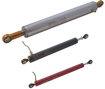 Alliance Sensors Group’s position sensors using linear variable inductance transducer (LVIT) technology offer analog outputs of both voltage and current loop, the most common of which are 0-10 Volts DC and 4-20 mA DC.
A voltage output is typically used in applications that have a receiving device, i.e.: PLC, DAQ system, or readout, located close by so the interconnecting wiring is not very long and can be shielded to prevent noise or electromagnetic interference (EMI) being coupled into the output.
There are several significant advantages to using a 4-20 mA DC current loop to transmit data over long lines from a sensor to a DAQ or control system instead of a voltage output. First, the current in the loop originates from a low source impedance, so the signal is much less susceptible to induced noise and EMI than any voltage signal. Current loop wiring typically can use twisted pair cables, which often don’t require shielding. Second, there is no degradation of the signal or losses over long connecting lines from line resistance, which will happen with a voltage signal. Third, it is usually possible to insert some other device, say for example, a local readout, into the current loop by simply connecting it in series within the loop.
A major benefit of a 4-20 mA output is the “live zero” at the 4 mA point (0% of the measured quantity) so the loss of a current, i.e.: 0 mA, would indicate a malfunction in the loop, typically a break in the wiring or a disconnected device and thereby is a fail-safe system diagnostic. Furthermore, an out-of-range loop current lower or higher than some specified value would indicate a malfunction in the system’s electronics, providing an additional system diagnostic.
A current loop consists of a 4-20 mA transmitter, a receiver with a loop load resistor across its input, the loop DC power source, and the interconnecting wiring for all these devices wired in series. ASG products with current loop output are 3-wire sourcing transmitters in which the loop and transmitter power comes from outside the loop, but they share a common ground within the current loop.
Using current loop output requires more care overall than a voltage output ordinarily would.
Three-wire transmitters are current sourcing, which means they drive current into the loop using DC power coming from the transmitter, so they must always connect to a sinking receiver input, where a loop load resistor is the only element involved. There is no DC power available from the input terminals of the receiving device. It is very important to never connect a 3-wire transmitter to a receiver input configured to work with a 2-wire or loop-powered transmitter because the 3-wire transmitter may be seriously damaged.
For any specified loop voltage, there is a maximum loop resistance that will permit full current to be developed in the loop. Exceeding the maximum loop resistance, which always includes the resistance of the field wiring, prevents the system from driving the full 20 mA (or higher) current into the loop. The loop load graph for a typical 3-wire current loop output sensor is shown in the figure below. At 24 Volts input, the recommended power supply for ASG sensors and modules, the total loop resistance can be as high as 850 Ohms.
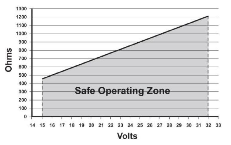
Maximum loop resistance vs. input voltage for a typical 3-wire current loop.
For more information, visit www.alliancesensors.com.
Share this information.
Related Posts
Dinkle Connectors for High-Density Wire Splicing
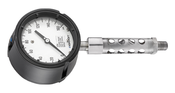
Webtec’s mechanical hydraulic tester offers increased flow capacity
New Mini-MicroTube Siphon Provides High Temperature Instrument Protection for Limited Space Installations
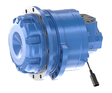
MCR8T Radial Piston Motor from Rexroth
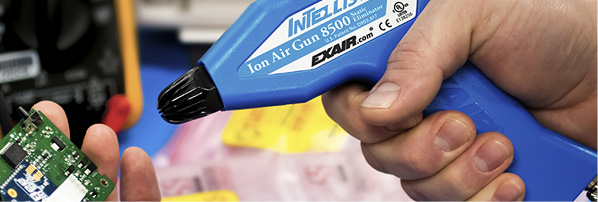
EXAIR’s Releases Intellistat Ion Air Gun for Sensitive Processes
AutomationDirect Releases D2-Series NFPA Tie Rods
Sponsor

Sponsors