Cycle Rates
20By Daniel Pascoe
In modern day manufacturing, quick cycle rates are key to profitability and eventual production facility success. This is no different in vacuum pick-and-place applications. Vacuum handling cycle rates (the speed at which a product is picked up, moved, and released) is often the measurement taken as to the effectiveness of selected components.
If handling large sheets of lumber or tiny electronic components, the cycle rates should be considered before anything else. How many parts per hour? How many parts per minute? The weight of a product being handled is often the first question asked but is rarely an issue as the surface area of the product is really smaller than that required to hold its weight with a vacuum cup(s). A single square inch of surface area can offer over 14 lbs of lifting force, for example.
One of the mistakes often seen is the installation of a large vacuum pump or generator that has been chosen to offer vacuum level achievement in the required time span for product pick up. However, different installation techniques and component choice offer a much more economical and sensible solution to quick, accurate, and reliable application success.
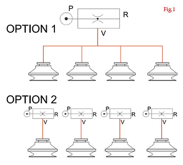 Fig. 1 shows two very simple options for a vacuum pick-and-place system. The port designations on the generator are P-compressed air supply, V-vacuum inlet port, and R-venturi exhaust port. Option One uses one vacuum generator (air-powered venturi) to supply vacuum to all four vacuum cups. The problem with this system, although low cost, is the evacuation time between the venturi and face of each vacuum cup. Each time the cycle starts, the generator has to start from zero and then create a vacuum in the now closed system (between the venturi inlet and cup face sealed against the product).
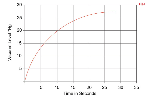
As shown in Fig. 2, which shows a venturi time chart for a known volume, the time taken to get to a safe working vacuum level could be the difference between success and failure. Depending on the generator chosen and particularly if the RED connecting tubing are long and of a large diameter, the evacuation time could be well outside of the user’s specification. Every manufacturer should provide evacuation timetables for this purpose. The exhausting of the vacuum (release of the product) is also extended, which will increase the total cycle time of the process.
Option Two shows the same vacuum cups, but each cup is attached to its own dedicated vacuum generator. This decreases the amount of tubing that needs to be evacuated, and if the generator is mounted directly to the cup, the tubing volume is removed altogether. However, using one generator per cup consumes more compressed air, and this could be considerable on some machinery that uses many vacuum cups in its process.
Vacuum pump manufacturers would argue that an electrical pump does not use compressed air, and this is a valid consideration in some cases where a compressed air supply isn’t available. However the pump cannot be mounted directly to the vacuum cup and often not even close, due to their physical footprint size and accessibility requirements for maintenance purposes. Capital cost of vacuum pumps is also higher than air-powered venturi systems in most cases.
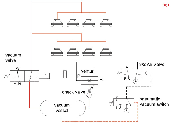
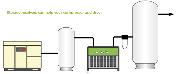
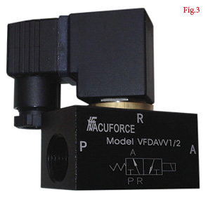 A solution for faster cycle times is the use of a vacuum valve (as shown in Fig. 3) and a reservoir or vessel. Vacuum valves can be mounted close to the vacuum cups with the vacuum source, be it a vacuum generator or pump, and can be placed at the base of the machinery. The vacuum vessel provides a storage medium that offers virtually instant vacuum to the cups as soon as the vacuum valve is actuated. Fig. 4 shows a circuit that uses a generator, storage vessel, and a vacuum valve.
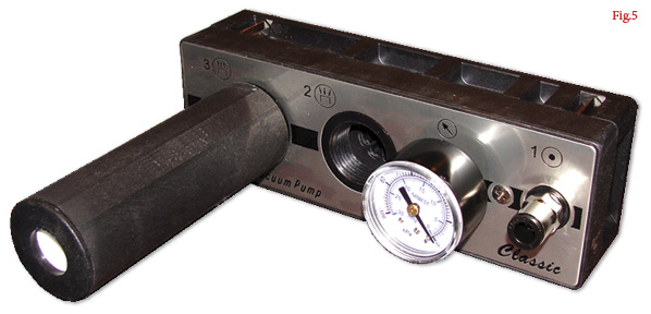
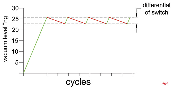
The generator cycles on and off using a pneumatic vacuum switch that is connected to the vacuum vessel. A more efficient multi-stage generator (compared to a single-stage unit) such as the model shown in Fig. 5 is also used. The generator only operates when the vacuum level in the system requires recharging. Fig. 6 is a graph demonstrating the cycling of the generator.
The first green line is the charge of the vacuum circuit. As the vacuum valve turns on and off, supplying vacuum to the cups, the vacuum level falls incrementally, as shown by the red line. The volume of tubing between the valve and the cups will determine how much vacuum is “used” and depending on the size of the vacuum vessel, how often the generator is turned ON. The switch used in this example has a differential of 3″Hg. The generator turns ON when the system vacuum level falls to 22.5″Hg and turns OFF when the system vacuum level reaches 25.5″Hg.
Therefore this system offers extremely quick “ready vacuum” to the cups and also minimizes compressed air consumption as the generator is only on when it needs to recharge the vessel. The same system can be used with an electrical vacuum pump. However, electrical vacuum pumps are normally coupled to a much larger vessel to prevent the pump from continuously cycling on and off, which is not good practice with electrical motors.
The vacuum valve as shown in Fig. 3 can cycle more than 10 times a second, so in extremely fast packaging lines for example, this method of vacuum control offers very rapid pick up and release of product being handled.
If this system is being used on a slower cycle rate application, the vacuum vessel will also offer a safety feature if compressed air is lost during the lift stage of the process. On non-porous surfaces such as steel or glass, this system could hold the part indefinitely without compressed air being present—a possible consideration, particularly when handling heavy or valuable loads or when personnel could be hurt by falling product.
As in any industrial application, there are many ways to achieve the finished result. The cost and effectiveness of these systems are open to discussion with many methods and components available for use from various manufacturers. The suggested method in the preceding text is simply one example of good component choice, where a fast cycle rate is achieved without unnecessary expense.
This article is intended as a general guide and as with any industrial application involving machinery choice, independent professional advice should be sought to ensure correct selection and installation.
Daniel Pascoe is President of Davasol Inc, an independent industrial consultant specializing in online brand presence and industrial e-commerce stores, with clients across North America and Europe, one of which is Vacuforce LLC (www.vacuforce.com) a manufacturer and distributor of vacuum components for whom this article was co-written with.
Daniel can be reached via www.davasol.com or directly at dpascoe@davasol.com. Find Vacuforce on twitter.com/vacuforce
Share this information.
Related Posts


Sponsor

Sponsors