Determining Root Causes
![]() We have read hundreds of incident reports in which some of the injuries were minor to several incidents that resulted in multiple fatalities. There are some very good investigators out there, however, there are very few investigators who are experienced enough with hydraulic systems and components to drill deep into the root cause. Language is a critical key in relaying the information to the reader, which could be anyone from the manufacturer of the equipment to the prosecuting attorney. Technical terms must be correct and expanded to the length necessary for the reader to understand. A well-written report made up of many details and contributing factors will greatly assist in preventative actions.
We have read hundreds of incident reports in which some of the injuries were minor to several incidents that resulted in multiple fatalities. There are some very good investigators out there, however, there are very few investigators who are experienced enough with hydraulic systems and components to drill deep into the root cause. Language is a critical key in relaying the information to the reader, which could be anyone from the manufacturer of the equipment to the prosecuting attorney. Technical terms must be correct and expanded to the length necessary for the reader to understand. A well-written report made up of many details and contributing factors will greatly assist in preventative actions.
“Is this the actual root cause?” Many factors lead to an incident, and the use of the fish bone diagram is an effective assist tool in assembling the facts. Generally speaking, a hydraulic incident will most likely, but not always, have a combination of the following contributing factors: component failure, failure to control hazardous energy, worker disregard, and unsafe machine design. Being responsible for the best outcome, an investigator should always dig and dig, but foremost the investigator should always utilize subject matter experts.
If a root cause investigation was only conducted by one person, we would have concern about how comprehensive the report may be. Company policy on incident investigations should include a “process of involvement,” meaning a minimum number of investigators and the knowledge each individual brings to the team. The team approach ideally is the most effective way to dig into root cause.
Hydraulic Safety Program
Hydraulics is simply a means of transmitting energy, and like all other forms of energy, there are associated hazards. Hydraulic hazards can cause injury, equipment damage, and environmental damage. Eliminating hazards and reducing risk requires a comprehensive process.
HSAC recently assembled a complete hydraulic safety program, which is a process designed to eliminate hazards, reduce risk, and make personnel knowledgeable. This combined process is the most effective way to protect workers, protect equipment, and protect the company from hydraulic hazards. Eliminating hydraulic hazards can be achieved by first understanding the causes and effects. Next is identifying hydraulic hazards, then integrating controls and devices, followed by developing specific procedures and training.
An Achieved Hydraulic Safety Program will contain some of the following elements:
- Integrated safety devices and components to execute energy control for task completions
- Integrated safety devices and components to protect equipment, environment, and personnel
- Developed procedures for energy control for specific tasks
- Awareness training and safe procedure training
- Documentation for inspection, hazard assessment, and protocol
Many elements are combined to build a full hydraulic safety program that will greatly reduce risk, and maintain reliability and long-term repeatability for equipment and personnel.
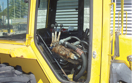
Answer: True, there is a high risk when exposed to hydraulic hoses. A hydraulic hose conducts energy, which is fluid that does work, and the resistance to flow generates pressure. The flexing of the hose is a result of spikes in pressure caused by resistance to flow. Should hose failure occur, the risks are impact from hose whip; fluid injection injuries; atomized fluid, which is highly flammable; associated equipment failure; slip hazards; and burns. Hose sleeves designed for safety, whip restraints, shielding, and guarding will reduce risk for workers. Failure can be reduced
through training, inspections, and proactive maintenance programs. The Earth Moving Equipment Standard ISO 3457 and EN 474-1 state that “Hydraulic hoses containing fluid with a pressure of more than 5 MPa (50 bar) and/or having a temperature over 50°C, and which are located within 1 meter of the operator, shall be guarded.” Every effort must be made to protect workers from hydraulic hose hazards.

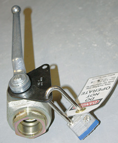
Answer: Isolation ball valves are commonly used where the hydraulic power unit is used to supply hydraulic power to many machines throughout the mill. Hydraulic supply, return, and drain lines to each circuit can be isolated while allowing other machines to function. There are many issues that increase risk with this method of isolation.
 Let’s start with leakage. Ball valves are designed having seat seals that can fail; therefore, the control of hazardous hydraulic energy would be lost. Next issue is lockable ball valves; the locking mechanism must not allow any swing of the valve handle. I’ve seen small padlocks locked into mechanisms where it was possible to swing the handle enough to allow the valve to flow. Next issue, some bleed circuits for energy control in the isolated circuit may be affected if the circuit is not allowed to vent energy back to the reservoir if the drain or return line is blocked. Redundancy of isolation ball valves will reduce risk if this method of energy control is used.
Also, it is very important that you verify zero hydraulic energy (flow creating pressure) beyond the isolation points. This means constant verification or a scheduled verification based on lapsed time over the period of the lockout. Be sure that the lockout procedure explains the importance of verification when using ball valves as a method of energy control.
* The above articles have been reprinted with permission. Images courtesy of Hydraulic Safety Authority of Canada, Inc.
For more information: The mission of Hydraulic Safety Authority of Canada Inc. (HSAC) is to provide proactive health and safety awareness programs specific to hydraulic systems and components. These programs provide a guideline for companies to follow as they show the necessary due diligence required for providing a safe work environment and improving their existing health and safety systems. Contact by phone: 416-363-7272; e-mail: info@hsac.ca; web: www.hsac.ca.

