Determining the Cause For A Cylinder Not Extending
There are three basic requirements to cause a double-acting cylinder to extend, as shown in Fig. 4.17:
- Flow must be supplied to the cap-end of the cylinder at a rate higher than any internal leakage.
- The available pressure at the cylinder has to be high enough to create the force necessary to overcome movement resistance. This resistance includes the load, any frictional resistance, and any back-pressure-related force.
- The rod-side fluid has to be able to escape.
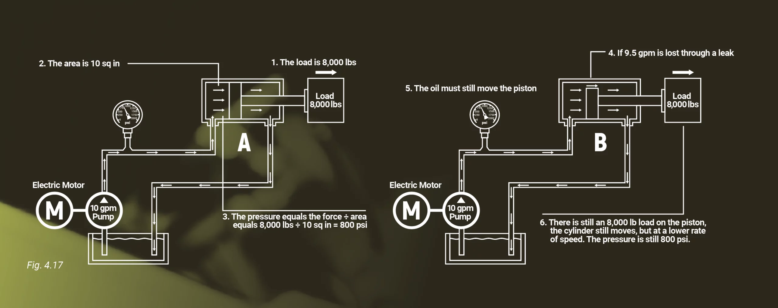
To cause the cylinder to extend, a source of flow, typically from the pump through a directional control valve, needs to be directed to the cap-end of the cylinder. If the cylinder seals or related valves are leaking excessively, the supply flow may pass through the leak points with only minimal resistance resulting in no cylinder movement.
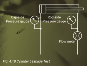
Installing a flow meter in series with the cylinder, as shown in Fig. 4.18, can assist in determining the extent of the internal leakage. If the cylinder is stalled and there is measurable flow through the flow meter, then the cylinder is leaking excessively. If the pump produces adequate flow and the cylinder is not bypassing, then a valve in the circuit may be bypassing or blocking flow to the cylinder.
The cylinder force required to move a load frequently changes as the cylinder extends due to changes in the mechanical advantage of the linkage. If there is excessive leakage, the resistance to flow may not be high enough to cause the pressure necessary to develop the required force through the full distance of the cylinder travel.
Pascal’s law can be used to calculate the theoretical pressure to overcome the load on a cylinder. Refer to Outcome 2.3.1 for additional information on Pascal’s law. The actual pressure to start and keep the cylinder moving is usually higher than the theoretical pressure. The added pressure is required to overcome the internal “stiction,” the static friction of the piston and rod seals. The friction of any pivot pins and sliding surfaces will require additional pressure to overcome the friction forces.
When the spool inside the directional valve is shifted, oil flow is directed to the cap-end port, and measured pressure should increase. Normally the measured pressure is the value necessary to overcome the load and is less than the maximum limit. If the pressure increases to the maximum, but the cylinder still does not move, the next step is to determine if the problem is due to excessive friction of the mechanical structure, an excessive load, excessive back-pressure, or damage to the cylinder.
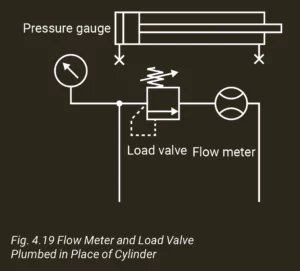
A flow meter and load valve plumbed in place of the cylinder, as shown in Fig. 4.19, can confirm that proper flow and pressure are being supplied to the cylinder. When adequate flow and pressure are available at the cap-end port with the load and friction determined to be within tolerances, but the cylinder still does not move, the rod-end pressure should be measured. Back-pressure caused by a load-holding valve or flow control will require additional pressure at the cap-end to overcome the additional force of the back-pressure working against the annular area. Plugged or crushed conductors can also prevent the rod-side fluid from escaping. Blockage of the rod exhaust may create a pressure exceeding the cylinder rating depending on the load and the cylinder ratio. Refer to Outcome 4.2.3 for additional information on cylinder ratio and potential intensification in cylinders.
A closed-loop control system with a faulty sensor can prevent the cylinder from extending either by sending a signal that the cylinder is already extended or, if an out-of-limit signal is present (too low or too high), a fail-safe condition may be triggered in the controller program. The fail-safe condition may either block flow to or from the cylinder or reduce the pressure setting of a pump compensator or relief valve.
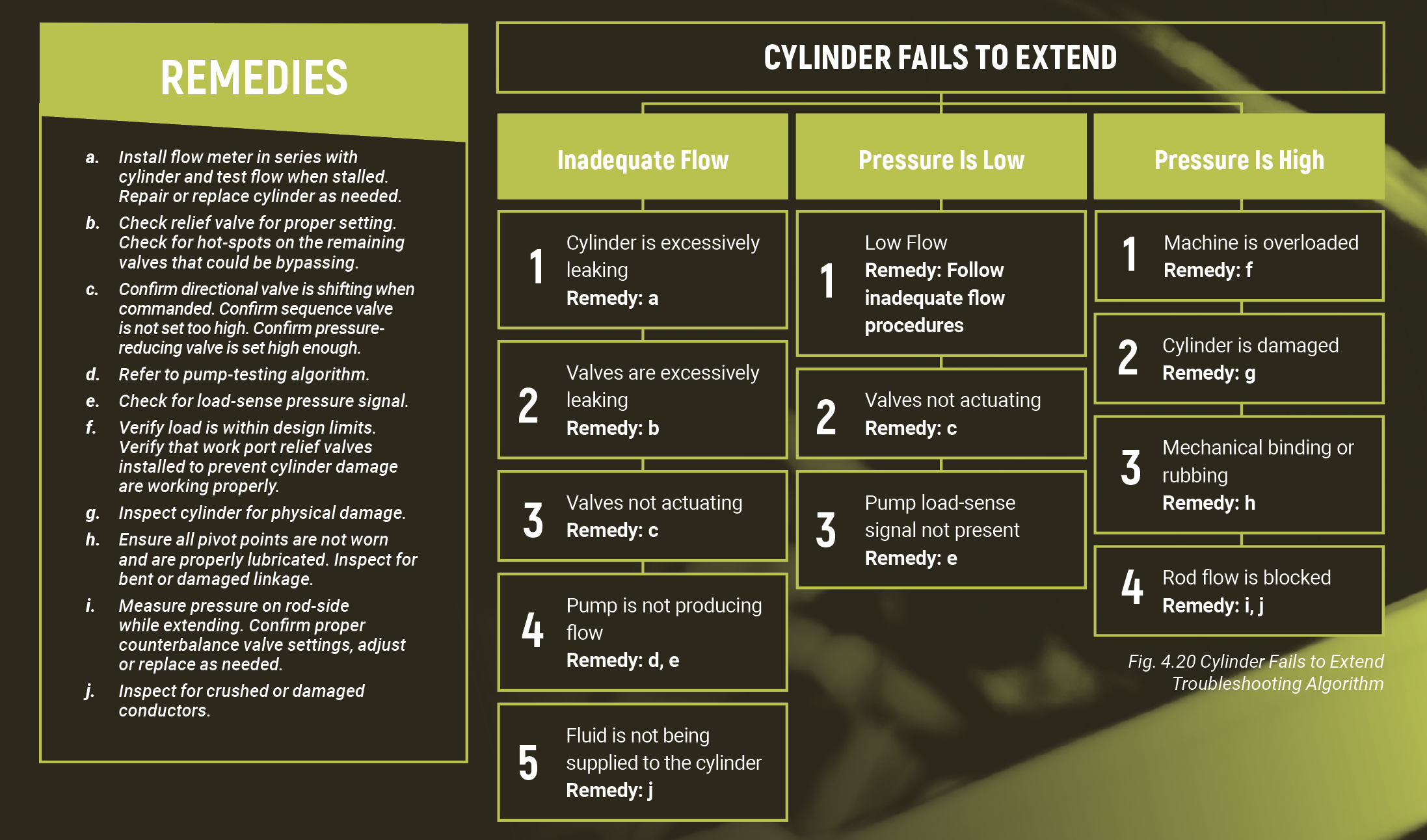
The troubleshooting algorithm shown in Fig. 4.20 provides basic diagnostic information on the common reasons a cylinder will not extend.
Test Your Skills
1. A retracted 2:1 area ratio cylinder in the circuit with pressure gauges and a flow meter connected, as shown in Fig. 4.18, does not move when the directional valve is shifted to extend the cylinder. The cap side pressure gauge indicates the full system pressure of 21 MPa (3,000 psi), the rod-side pressure gauge indicates 42 MPa (6,000 psi), and the flow meter reads 0 lpm (0 gpm). What could be the most likely cause?
A. The directional valve is not shifting to direct flow to the cylinder.
B. The piston seals are leaking excessively.
C. The cylinder pins are most likely dry and need to be lubricated.
D. The cap-side counterbalance valve is set too high and is blocking flow.
E. The rod-side flow is not being exhausted.
2. A partially extended cylinder in the circuit with pressure gauges and a flow meter connected, as shown in Fig. 4.18, does not move when the directional valve is shifted to extend the cylinder. The cap-side pressure gauge indicates 10 MPa (1,500 psi), the rod-side pressure gauge indicates 1.5 MPa (220 psi), and the flow meter reads the rated pump flow of 30 lpm (8 gpm). While extending, the system pressure is normally 21 MPa (3,000 psi). What could be the most likely cause?
A. The rod-side counterbalance valve is set too low, allowing the fluid to bypass the cylinder.
B. The system relief is bypassing all the pump flow.
C. The cylinder is leaking excessively.
D. The cylinder rod is bent and causing the cylinder to bind.
E. The cylinder rod pins are dry and need lubrication.
3. A cylinder begins to extend, but stalls almost immediately before it reaches full extension. A pressure gauge installed in a cap-end test port reads 31 MPa (4,500 psi), and a pressure gauge in a rod-end test port reads 0.2 MPa (30 psi). When the plumbing is changed, as shown in Fig. 4.19, the flow and pressure developed are at the rated values of 15 gpm and 4,500 psi. Which of the following is a likely cause?
a. The load is too high.
b. The pump compensator is set too low.
c. The cylinder’s piston seals are leaking excessively.
d. The pivot pins are over-lubricated.
e. The directional valve is not shifting to supply fluid to the cylinder.

