Figure It Out: Hydraulic Motor Slows as Accumulator Discharges
By Robert Sheaf, CFPAI/AJPP, CFPE, CFPS, CFPECS, CFPMT, CFPMIP, CFPMMH, CFPMIH, CFPMM, CFC Industrial Training
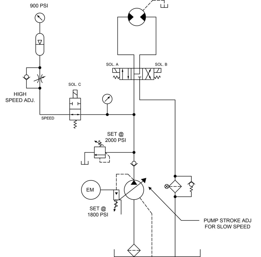
 A new system was required to run a hydraulic motor at a constant high speed for a short time in one direction, and then run at a slow speed in reverse to pick up another batch for loading into the system.
The circuit shown with the
A and B ports connect in the center position was used to prevent the motor from drifting and provided quicker response. The designer used an accumulator circuit since there was idle time between cycles to recharge and allow them to use a much smaller pressure compensated pump with a stroke limiter for slow reverse speed.
The pressure to rotate the motor with a load was approximately
950 psi (65.5 bar). A five-gallon accumulator was needed to supply the two gallons of flow required to supplement the pump output to rotate the motor at the constant speed required. The nitrogen precharge was 900 psi (65.5 bar) with the pump compensator set at 1,800 psi (124 bar). Solenoid C was energized only when the motor was reversed.
They had problems getting the motor to run forward at a constant high speed. The motor would start turning at the needed speed but continued to decelerate as the accumulator charge gauge dropped off.
What could be the problem?
See the Solution


