Fluid Power Faux Pas: Top 5 Hydraulic System Mistakes
By Cindy Cookson, Vice President of Hydraulics Global Product Line Management, Gates Corporation
With decades of experience in hydraulics, my Gates colleagues and I, especially our application engineers, have seen a lot when it comes to hose, coupling, and tubing solutions. At one end of the spectrum, we’ve been impressed, even inspired, by the ingenuity and creative problem-solving applied by end users. But at the other end of the spectrum, we’ve witnessed errors that make us cringe when we see them repeated in the field. To help everyone in our industry avoid these costly missteps, our friends at Fluid Power Journal asked us to share our top five hydraulic-system mistakes and some thoughts how to avoid them.
1. Forgetting about safety
When working with hydraulic systems day in and day out, some users become complacent about safety. Or even worse, technicians new to hydraulics may see a hose and mistakenly consider it to be the equivalent of a garden hose. In high-pressure hydraulics, mistakes can lead to critical injuries or even death, so it’s important to never take a hydraulic system for granted. Here are some critical safety reminders about hydraulic systems and hose assemblies:
- Never touch a pressurized hydraulic hose. Rubbing your hand along a hose as a leak-detection technique, for instance, is just asking for trouble.
- Similar to electrical systems, hydraulic systems can be energized even when the system appears to be “off.” Therefore, always depressurize a hydraulic system prior to handling or replacing any system components.
- When replacing a hydraulic assembly, always ensure the replacement assembly can meet the system performance requirements, including working pressure, temperature, and fluid being conveyed.
- For hydraulic hand tools, never carry the hand tool by the hose. This can lead to pinching and pinholes.
- For line-of-sight hydraulic lines in which an operator is working near the pressurized hydraulic assembly, use line-of-sight sleeving to protect the operator in the case of hose or assembly failures.
2. Relying on ‘what we’ve always used’
Hose and coupling standards for hydraulic systems have evolved over time. System pressures have increased, and the loads on hydraulic systems are increasingly dynamic. Meanwhile, materials science and process technologies have improved the capabilities of hydraulic hose and coupling assemblies.
Relying on “what we’ve always used” misses out on innovation and improvements in hydraulic hoses and couplings. But it could also mean compromising the safety of a hydraulic system. Hose and coupling selections should be made based on system requirements and not just on a hose construction. We often hear, “I need a two-wire braid hose,” or “my system needs a four-spiral hose.” But as OEMs have transitioned to isobaric hose ratings and hose manufacturers have innovated to deliver flexibility and weight savings in hydraulic hoses, referring to a hose by its construction is a risky move. Instead, when selecting hoses and couplings, follow system requirements for working pressure, temperature, and fluid compatibility.
The STAMPED method reminds users of the considerations for selecting a hose for a specific application. Here’s a brief explanation of the STAMPED acronym:
- Size – Determine what ID hose is required for fluid flow. A hose that is too large reduces system performance due to increased pressure loss and excessive system heat from excessive fluid turbulence.
- Temperature – The hose must be capable of withstanding the system’s minimum and maximum fluid and ambient temperatures.
- Application – How and where the hose assembly will be used.
- Material/Media – The hose tube, cover, and couplings must be compatible with the fluid being conveyed.
- Pressure – Published hose working pressure must equal or exceed the normal system pressure, including pressure spikes.
- Ends – Identify the termination and threads needed for the system to define the proper couplings and adapters.
- Delivery – Determine the hose size needed to deliver the required fluid volume without losing pressure or adding unnecessary weight or bulk. Also consider requirements for how the hose and assembly are physically provided to the end application, including the date required, special packaging, labeling, or certifications.
3. Poor system routings
 Hose assembly routings are a critical component of hydraulic system performance, both in an OE application and when replacing hoses. Poor routings can lead to, at best, an under-performing hydraulic system with less system pressure than expected; or at worse, faulty routing leading to costly downtime, with the worst-case scenario being unsafe working conditions. Application engineering experts can diagnose a hydraulic system and recommend routings or system changes to improve performance, and these consultations usually reduce hydraulic system costs (figure 1).
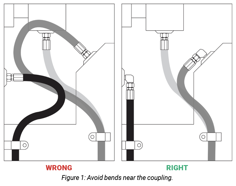
Because hoses are flexible, they are often chosen instead of rigid tubes. But that doesn’t mean hoses have unlimited flexibility. Common issues arise when hoses must bend – particularly bends near the coupling. Optimized hose routings will avoid hose bends near the coupling by using angled adapters or alternative coupling options to alleviate hose flex requirements. If a bend radius is below the recommendation for that particular hose, get creative with angled adapters. Revisit your coupling selection to avoid sharp bends (figure 2).

Proper routings also mitigate hose abrasion, whether against other hoses or against machine components. Return lines are another component that can be problematic. Although the lines are typically low pressure and a necessary component to return fluid to a reservoir, they are often the last component considered when designing a system. To mitigate the risks of challenging routings, Gates makes Multi Master GMV MegaFlex, a flexible, corrugated hose design that has a tighter minimum-bend radius. Finally, hose routings can minimize the likelihood of leaks in a hydraulic system with proper termination selection. Avoid stacking adapters to minimize system cost and the risk of system leaks.
4. Ignoring signs of wear
Hydraulic assembly inspection should be included in any preventive maintenance schedule. These inspections should monitor for signs of wear, including cover damage like cracking and abrasion. Ideally, the system design reduces the likelihood of damage, but when damage reaches the hose reinforcement, replace the assembly.
Cover cracks can be caused by several issues. Exposure to extreme heat, particularly in engine compartments, can cause the exterior cover of the hose to become brittle and crack (figure 3). Exposure to ozone, either from the sun or from high electrical charges, such as in welding equipment applications, can cause microcracks to appear on the surface of the hose. This is similar to the weathering seen in tire sidewalls. Ozone damage typically appears first on the exterior of hose bends, where the rubber compounds see their highest stresses. Once these cracks reach the hose reinforcement, the reinforcement is compromised because of potential damage from moisture and debris. This damage can be mitigated by protecting hoses from high electrical exposure and by choosing hoses with materials resistant to ozone.
 Cover abrasion is a constant challenge, particularly in congested hydraulic systems where it is difficult to isolate one hose from others or the machine frame in dynamic applications. The most obvious way to mitigate abrasion damage is to choose hose covers that are specially formulated with abrasion resistance. Specialized nitrile rubber compounds offer a midgrade level of abrasion resistance, and extreme resistance to abrasion can be realized with a hose cover made of ultrahigh molecular-weight polyethylene film. It is also possible to assemble the hose in an abrasion-resistant sleeve or hose guard, but this option considerably increases assembly costs and can complicate hose installation in the application.
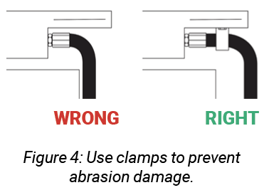
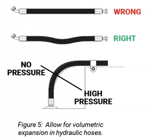 In addition to selecting abrasion-resistant hose covers or accessories, the hose routing can also have an impact on hose abrasion. Use clamps to support long hose runs or to keep hoses away from moving parts, taking special care to allow for volumetric expansion. Hoses that bend around a portion of the machine frame should be assembled with enough length to avoid rubbing over a machine corner. And it’s worth noting that hoses should never be clamped to the machine frame, which could restrict expansion in the curves when the hose is pressurized (figures 4 and 5).
5. Proper assembly
A user can procure the most premium and highest-performing hoses and couplings in the world, but if they’re not assembled correctly, they’ll never realize the value. Proper assembly has several criteria: a qualified hose-coupling interface, assembly by a trained technician, and a verified crimp diameter.
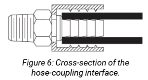 A qualified hose-coupling interface results from verifying that the hose and coupling work together. The verification is more than just crimping to a certain crimp diameter; it should be verified by burst and impulse testing across a range of crimp diameters to account for hose and coupling manufacturing variation as well as crimper and die tolerances. The testing should mimic the intended application, particularly the temperature. A hose-coupling interface may work well at standard 100°C (212°F) operations and then not perform at elevated temperatures above 120°C (248°F). Further, all hoses are not the same. Even though hoses from different manufacturers may meet the same performance criteria, the properties of the compound affect the robustness of the hose-coupling interface. Also, the thickness of the rubber materials and the placement of the reinforcement material can change the crimp dimensions. Likewise, couplings from different manufacturers are not necessarily equivalent. They may be made from different grades of steel, different material hardness, and include features such as serrations that are dimensionally different and may significantly impact the quality of the hose-coupling interface. Even the radius or heights of these features can significantly impact assembly performance (figure 6).
 A trained assembly technician is also critical to the assembly process. She or he must be trained to select the proper hose and couplings, cut the hose to the correct length, remove debris and contaminants from inside the hose, ensure full coupling insertion onto the hose, select the appropriate crimper setting, and place the assembly properly in the crimper dies. And the technician must do it all safely!
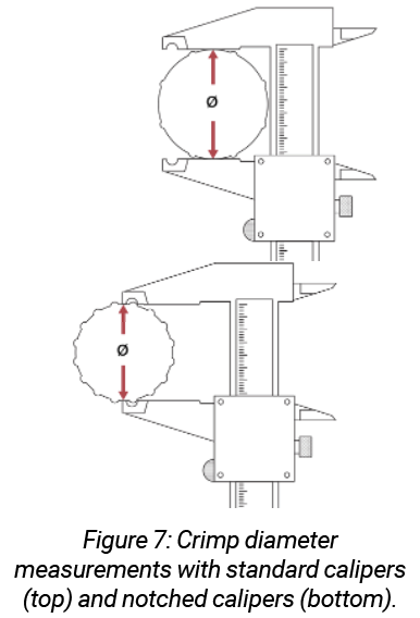
Finally, after the assembly has been made, the crimp diameter on each end of the assembly must be verified for proper crimping. This measurement is often performed with calipers and compared to a qualified crimp diameter range (figure 7). Some systems also use a go/no-go gauge to verify the crimp by reviewing either the crimp diameter or the stem collapse.
Smart crimpers are gaining popularity in the market. They make operator training and quality assembly easier by mistake-proofing various steps in the assembly process. Smart crimpers, such as Gates’ GC20 Cortex crimper, typically include the crimp settings in an onboard computer to eliminate the need to reference the crimp setting and program the crimper.
New technology and materials are advancing the capabilities of hydraulic hoses and couplings, as well as hydraulic systems overall. As hydraulic systems become more complex, proper hose routing keeps the system running efficiently, both in OE and replacement applications. Baseline training in hydraulics can support safe operations and provide reminders on system inspections. Finally, hose and coupling manufacturers often provide recommendations and training on proper hose assembly. Staying up to date on these innovations and recommendations is well worth the effort, as it can promote a fluid power system’s safe operation, improve its performance, and reduce downtime.
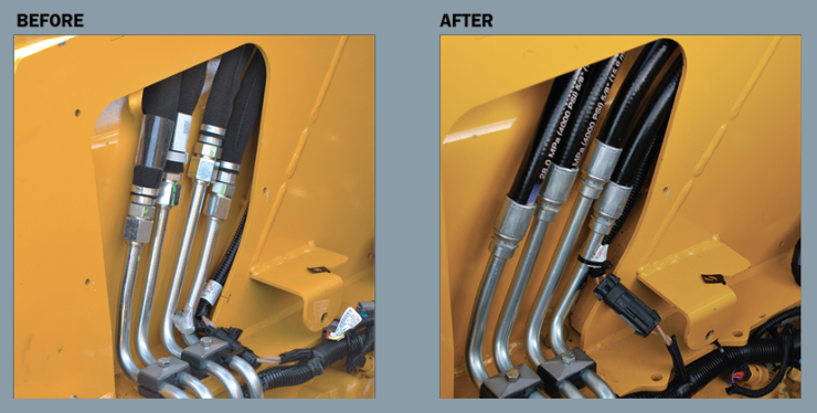
Case Study: Optimizing Hose Routings
Two case studies by Gates product application engineers demonstrate the value of optimized system-hose routings. In the first case, a customer was having difficulty routing hoses through a channel in the rear drive. Upon further inspection, Gates engineers found a few opportunities:
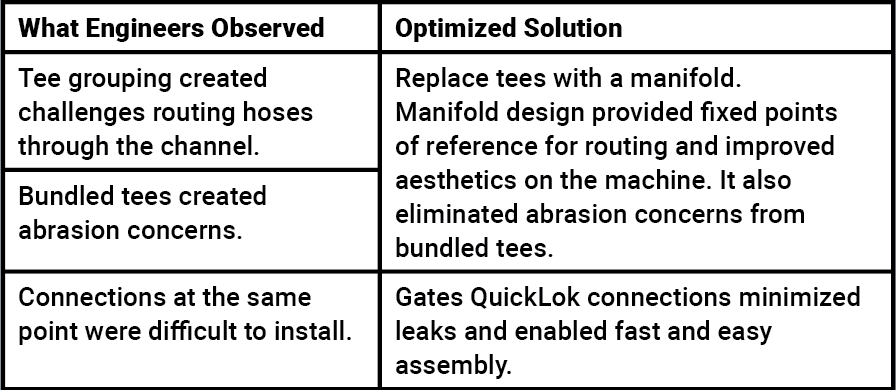
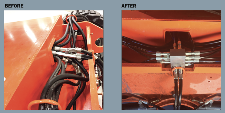
The before-and-after photos show a cleaner system with improved performance and fewer leak points.
In a second case, a customer had issues with hydraulic fluid leaks at a hose-tube connection point. The Gates engineer located the root cause of the leakage issue: a bundle of hose-tube connections that were difficult to get wrenches on caused installation challenges and system leaks. The solution was crimp-on hose-tube connections that eliminated the leaks and reduced the number of SKUs.
Share this information.
Related Posts
Locking Protection is Key to Hydraulic System Safety

2018 Off-Highway Directory Listing

All Around the World: Circular Sustainability for Fluid Power
Pneumatics Gets a Grip on Robotic Tooling Applications

Bosch Rexroth Valve Platform Offers Modular Control for Mobile Machines
Don’t Forget to Celebrate!
Sponsor

Sponsors