Foam Injection Machine Overheats
By Robert Sheaf, CFPAI/AJPP, CFPE, CFPS, CFPECS, CFPMT, CFPMIP, CFPMMH, CFPMIH, CFPMM, CFC Industrial Training.
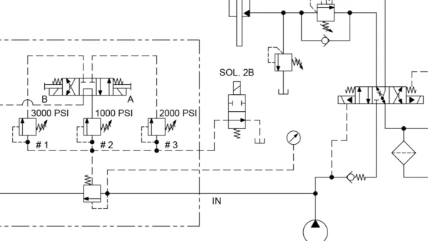
Many people don’t quite understand “Slip in logic cartridge” valves. The attached circuit is a good example showing a solenoid unloading relief valve. When energized, the valves directional valve relief poppet will open at its maximum 13.8 MPa (2000 PSI) setting and de-energizing the directional control valve will allow flow to return to tank with a very low pressure drop.
The problem with the machine overheating seemed to be caused by the relief not unloading when the solenoid operated valve is de-energized during the idle cycle. This causes the full pump flow to return to tank at 13.8 MPa (2000 PSI) pressure drop across the valve’s poppet. This was adding approximately 7° C (14 °F) temperature increase in the flow going back to the tank. The cooler was not designed for this amount of heat being generated.
Examining the directional valve and main relief poppet showed no signs of malfunctioning or sticking.
What would you do next?
See Solution
Robert Sheaf has more than 45 years troubleshooting, training, and consulting in the fluid power field. Email rjsheaf@cfc-solar.com or visit his website at www.cfcindustrialtraining.com. Visit fluidpowerjournal.com/figure-it-out to view previous problems.


