Gauge Ports Make Life Easier
By Robert Mackey, General Manager, MAIN Manufacturing Products.
Some time ago, at CONEXPO-CON/AGG, it was possible to climb a stepladder, pass through a hatch, and sit next to the hydraulic brake motor of a large dump truck. However, just looking at the motor gives you less information about what is happening to the system than a diagnostic port.
In the last show, a vendor set up a stage with joysticks, gauges, and video screens for visitors to operate construction equipment several states away in real time. The conditions this equipment operates in could be the cold of the Arctic Circle to heat of the Sahara Desert. The equipment could be 5,000 feet under the ocean surface or in outer space. Note that the Colorado School of Mines now offers degrees in space resources (mining on asteroids). It is vital to know what is happening to the hydraulic components and fluids in this equipment. One way to do this is to extract a sample of the fluid or measure the fluid’s pressure and temperature. This article discusses the requirements of diagnostic gauge ports and explores available components to make life easier. MAIN Manufacturing Products has been putting gauge ports in flanges and making gauge port adapters for decades. MAIN has made flanges for over 65 years and participates in the SAE and ISO technical committees so we can speak of the market with confidence.
One of the first places to start is SAE J1298 Hydraulic System Diagnostic Port Sizes and Locations. This document was stabilized in 2016 by the SAE FCCTC subcommittee and is the consensus of fluid power manufacturers, OEM equipment manufacturers, and users. Stabilized means that the standard does not need regular review, as it is the best information currently available. It is not identical to ISO 8925 because SAE J1298 has additional metric and inch connections. SAE J1298 gives requirements for the manufacturers of self-propelled work machines and recommendations distilled from much discussion. Indoor equipment like presses and molding machines may not need the larger diameters of gauge ports specified, but the locational information in the standard still applies. It is a good idea to have a copy of the standard as it contains additional requirements. SAE J1298 covers only ports, not fittings, which have their own standards.
One of the first items to think about is what type of gauge port is needed. SAE J1298 requires M14 x 1.5 (ISO 6149), 3/8-18 (SAE J1926/ISO 11926 (SAE straight thread)), or SAE J518 flange ports for larger sizes. The “/” represents that SAE J1926 and ISO 11926 are generally technically identical. At MAIN, we see, in order of market preference:
- NPTF
- SAE straight thread
- BSP (P or T)
- ISO 6149
MAIN manufactures flanges with gauge ports daily. The industry is trying to move to using elastomeric sealing specified in the SAE straight thread (SAE J1926) and ISO 6149. Metal-to-metal sealing, like the NPTF and some BSP threads, is discouraged because of its tendency to leak, although usage is very common.
Next is the size of the port. At MAIN, the 1/4 inch (#4) size is the most common, with 3/8 (#6) next. ISO 6149 ports are not common but MAIN does machine these in. The 9/16-18 thread corresponds to the #6 SAE straight thread size. SAE J1298 says for temperature, pressure, and sampling, the size should be the M14 X 1.5 ISO 6149 or the #6 SAE straight thread. It uses the larger size to improve fluid flow in colder situations. MAIN was involved with a distributor that was reconfiguring equipment that was transferred from oil fields in Alaska to oil fields in Saudi Arabia. When designing equipment, it is important to consider the life of the equipment and all possible environments in which the equipment could be used. Appropriately larger sized ports can also be used to measure flow.
Ports should be located in places to get the most accurate readings. This is generally in the fluid stream. A requirement of SAE J1298 is to have at least one port at the main system relief valve. Other suggested places are the inlet and outlet ports of the following locations:
- pumps
- valves including work ports
- filters
- actuators
- all systems with relief valves
It is a good idea to consider the requirements of OSHA, or other nations’ equivalent organization, of assuring that the system is de-energized before working on it. Although gauges can malfunction or break, showing zero pressure on each side of a hydraulic component is a first step to assuring no hydraulic pressure in the component.
Finally, around the diagnostic port make sure that there is at least a 3 inches (75 mm) diameter and a 8 inches (200 mm) high area of no interference to allow for clearance for the connection to be made. This space allows the gauge or coupling to be installed. A type of fitting to consider is the push-to-connect under pressure fittings. These are hydraulic fittings designed to allow coupling and decoupling under pressure. With this fitting, gauge or sampling equipment does not have to be attached to the system at all times, or even most of the time. Many companies manufacture push-to-connect under pressure fittings, and they are available from many sources and can make the determination of location easier.
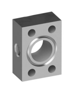
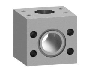
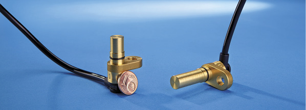
In-line flange with gauge port.
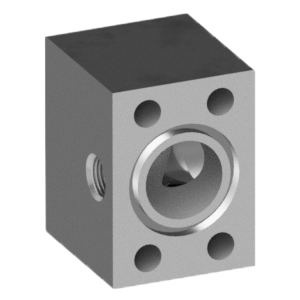
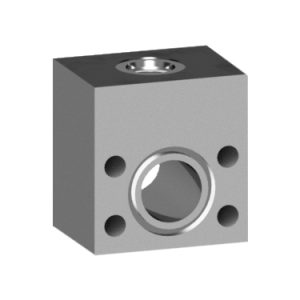
Elbow flange with gauge port.
Options for adding ports
Where to locate the diagnostic port or gauge is not the same question as how to install gauge ports into the system. In some cases, the component manufacturer may offer a port option on the component. The orientation may not be ideal for the system, but the component manufacturer knows where a port can safely be added. Adding ports to component may be expensive, delay delivery, or cause other problems, and not all components have gauge port options. Most flange manufacturers can machine gauge ports into flanges inexpensively. Flanges are normally good spots to put the port, as these locations are generally in more turbulent sections of the piping. Orientation can be a problem on smaller sizes.
The gauge ports can only go into two sides for in-line and elbow connections. This is because the bolt pattern of the flange is rectangular, and there is not enough room on smaller sizes to go through the narrow side of the bolt pattern. The ports must be located on the long side of the bolt pattern or the block size changed and the through hole of the diagnostic port reduced. Getting the clearance space discussed above could be a problem with the straight connections but is generally less of a concern with elbows. MAIN stocks many flanges with gauge ports, and all styles are offered with gauge ports. In some cases, the flange dimensions have to be adjusted, but otherwise it is very cost effective to install gauge ports.
Saddle weld flange.
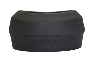
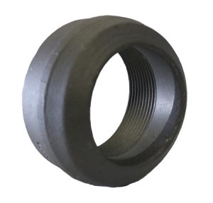
Threadolet side and front views.
Weldolets and threadolets are available for welding onto a pipe run near the component. Weldolets and threadolets are cylindrical-shaped steel components that have a circular cutout perpendicular to the axis of the cylinder on one end and are ported at the other end. The circular cut out section looks like a saddle, and the fittings are sometimes called saddles and the weld a saddle weld. The circular cutout’s diameter matches the pipe or tube diameter to which the adapter is being attached.
The number of needed pipe diameter sizes makes stocking the adapters challenging and expensive. Installation involves bringing a welder to the location, drilling the hole, and cleaning the pipe after the welding. Although not cataloged, MAIN will machine special saddle welds for quick shipment.
Flanged run tee.
Reducing straight thread run tee.
Another common way to get a port into the system is to put a tee into the hydraulic line. This works well on smaller lines, although reducing tees can be harder to find and have slower delivery. This solution works even with hydraulic flanges. For larger lines and bigger take-off ports, reducing run tees can be used. Similar to the gauge port adapter plates discussed below, the reducing run tees are blocks with #12 or #16 SAE straight threads or other ports. They are regularly 2 inches or more thick.
While the run of the tee can be made in any port style, most are straight threads, flanged (having a flange port), then NPTF.
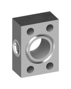
Thread gauge port adapter.
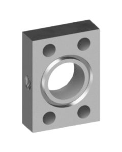
NPTF and SAE St.
Another convenient way to add a gauge port to hose or pipe with flange ports is with gauge port adapters. Gauge port adapters are plates between 1 and 1.5 inches thick, ground on one side and O-ringed on the other. A gauge port is put in the side of the long way of the bolt pattern. Some manufacturers put an NPTF on one side and an SAE straight thread on the other side.
Gauge port adapters have the appropriate bolt pattern for the size of the flange. These parts get sandwiched in between the flange fitting and the component using longer screws. No machining is required and the port can be added very quickly in retrofit situations. The thickness of the plate is determined by the size of the gauge port. Many manufacturers offer these from stock in popular sizes and ports. MAIN has gauge port adapter plates stocked in all popular sizes, such as 1/4-inch and 3/8-inch NPTF, and #4 and #6 SAE straight thread. BSP (T or P) in 1/4 or 3/8 inch are manufactured regularly with very quick delivery times. The ISO 6149 ports are not as common in the U.S. MAIN has quick delivery times on them but many manufacturers and distributors do not stock them or have even offer the plates with ISO 6149 ports.
For system maintenance and troubleshooting, not all the systems have gauge ports where needed. The gauge port adapters lend themselves for use by maintenance workers and distributors trying to troubleshoot a system. They organize sets of adapters with longer screws and a gauge and putting this group into a pelican type case. When the troubleshooter arrives, they sandwich the gauge port adapters in-line with the gauge installed and get the information or sample they need to quickly and precisely analyze the system.
Share this information.
Related Posts


Sponsor

Sponsors