Transforming Our Thinking About: Energy Units

By Dan Helgerson, CFPAI/AJPP, CFPS, CFPECS, CFPSD, CFPMT, CFPCC
We are taught to think of fluid power in terms of flow and pressure; flow is for velocity and pressure is for force. While this is true at the actuator (the motor or cylinder), the terminology may have limited us in our approach to energy transfer. It is necessary to separate flow and pressure in the initial calculations for what is required for the actuator. The required speed will determine the rate that fluid enters the actuator. The force required will determine the pressure of that fluid. This is pretty straightforward, and it provides necessary information when using a single-fixed flow to drive a single-fixed load.
However, when there are variable loads, variable speeds, and multiple actuators, separating flow and pressure may limit us when we apply it to the source (the receiver, accumulator, or the pump). This is where the concept of energy units and the use of displacement transformers, either variable (VDT) or fixed (FDT), can be used to better understand how to cause an actuator to draw only the energy units needed from the source.
What is an energy unit? An energy unit is a unit volume of fluid that is charged with a unit pressure. While it is true that pressure and flow are two distinct qualities when transmitting energy through fluids, the two cannot be completely separated. Without pressure, there would be no flow. Without flow, there would be no movement. It is the combination of flow and pressure that produces work. In fact, it is the combination of flow and pressure that defines work. In this article, the cm3 and the in3 will be the unit volumes. The MPA and the psi will be the pressure units. The metric energy unit will be MPa/cm3. The U.S. Customary energy unit will be the psi/in3, which is the same as the in.lb.
When energy units are used to overcome a load, work is done. Energy units can exist as potential energy when stored in an air receiver or a hydraulic accumulator. They can also exist as kinetic energy when released from a receiver, accumulator, or driven by a pump. Work describes the number of energy units used, while power describes the rate at which those energy units are used. In this article, we will look at an example that only deals with the work being done. In later articles, we will look at power control where the FDT and the VDT can be used to limit the kinetic energy drawn from the source.
Below is a common example of an application where there is a single source, but a variable load requirement. We are going to look at the energy units needed to do the work and compare them to the energy units used to do the work.
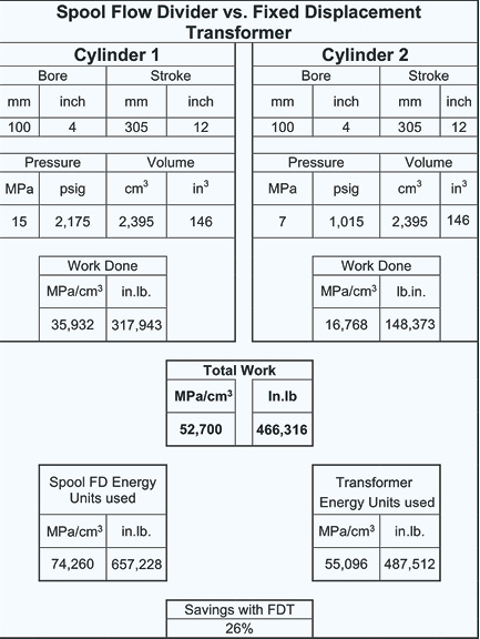
Two cylinders with a bore of 100 mm (4”) and a stroke of 305 mm (12”) need to be synchronized. Each has a different load; one requires 15 MPa (2,175 psi) and the other 7 MPa (1,015 psi). Thinking in terms of energy units, we see that lifting the larger load will require 35,932 MPa/cm3 (328,233 in.lb.) and lifting the smaller load will require 16,768 MPa/cm3 (153,175 in.lb.) of work.
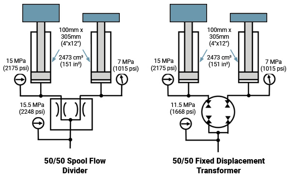
We will compare a spool type 50/50 flow divider valve to a two-section fixed displacement transformer (FDT) to see which is the most efficient in terms of drawing the least number of energy units from the source.
The spool flow divider will split the flow evenly so that each cylinder will receive a volume of 2,395 cm3 (146 in3). The total volume to fill both cylinders is 4,790 cm3 (292 in3). The spool flow divider alters the pressure at each outlet. It cannot intensify pressure, so the input pressure to the valve must be greater than the maximum pressure requirement of the cylinders. The pressure drop through the valve must be added to the pressure required to lift the greatest load. In this case, the input pressure will be 15.5 MPa (2,248 psi). For the cylinder with the greatest load, the pressure drop through the valve is 0.5 MPa (72 psi). For the cylinder with the lighter load, the pressure drop is 8.5 MPa (1,232 psi).
The chart below shows that a total of 74,260 MPa/cm3 (657,228 in.lb.) of potential energy was taken from the source to do that work.
When the FDT is substituted for the spool flow divider valve, there is a very different outcome. The FDT also divides the flow equally, but it does not require the pressure of the greatest load. Instead, its input pressure requirement is the average of the load pressures plus some pressure drop to rotate the FDT. It requires only 11.5 MPa (1,668 psi) to drive both loads, drawing only 55,096 MPa/cm3 (487,512 in.lb.). According to the chart below, the FDT requires 26% fewer energy units than the spool flow divider.
The FDT is able to do what the spool flow divider cannot do; it can intensify pressure and distribute energy. The FDT is made up of two equal, positive displacement chambers that are mechanically linked. Pressure at the inlet of the FDT induces a torque on the connecting link. The torque is used to drive the fluid to the load. Any torque that is not required by the load on one side is transferred to the load on the other side. The positive displacement equally distributes the flow while the connecting link distributes the torque. The result is an input pressure that is the average of the two output pressures.
The spool type flow divider must receive enough energy to drive both loads at full pressure. It then consumes the extra energy for the lighter load by forcing the fluid through an orifice, squeezing off the pressure and releasing the energy as heat. The FDT receives only the energy needed to do the work and then distributes the proper amount of energy to each load.
If you have any questions, please contact Dan Helgerson at Dan@DanHelgerson.com.
Share this information.
Related Posts


Sponsor

Sponsors