Hold It Down – Vacuum Clamping
By Daniel Pascoe President of Davasol, Inc.
 Most of the articles I have authored for Fluid Power Journal have been about vacuum pick and place, which is the most common application in fluid power circles for vacuum components. However, a relatively common application for the same components is the opposite of pick and place: material hold down or vacuum clamping.
Industries such as sign manufacturing, glass production, fiberglass fabrication, aerospace CNC machining, and automotive trim finishing, all utilize vacuum hold down in some way or another. This article discusses the basic methodology used in achieving a secure, safe and energy-efficient system to employ in these various applications. All vacuum clamping installations should involve the same fundamental criteria: rigid hold down without movement of the work piece during production process, ease of capture and release of the product, and, of course, fair cost of purchase and operation for the end user.
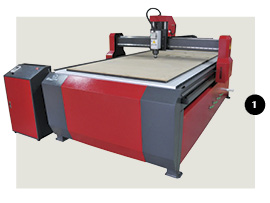
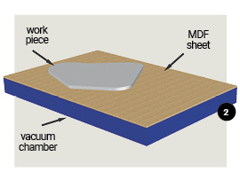 CNC routers such as the model shown in Fig 1, utilize a porous vacuum bed usually made from MDF (medium density fiberboard) which covers the complete machining area. Work pieces, such as plastic sheets, are laid flat against the MDF board and a large flow vacuum pump, usually an oil-free sliding vane pump or regenerative blower, are connected to a chamber directly underneath the MDF sheet. Vacuum is pulled through the MDF and, in doing so, holds the work piece(s) against the surface. Of course, the greater the surface coverage, the greater the vacuum level (less leakage) and consequently the holding force. Fig 2 illustrates this. The area of the MDF not covered by the work piece may have to be covered by thin plastic sheet to minimize leakage, therefore maximizing the vacuum force holding the work piece.
The holding force is entirely dependent on the vacuum level achieved by the vacuum pump. This is the reason high flow pumps are used on CNC routers. For example for every square inch of work piece the theoretical holding force will be 14.7 lbf at 100% vacuum (29.92″Hg). Consequently if the vacuum being achieved is only 3″Hg (due to expected leakage through the MDF) the holding force will be reduced by 90% which equates to 1.47 lbf . This might be enough for a machining process such as simple hole drilling, but if there is a large side force during profile machining, the vacuum level may need to be higher. This is when the open area of the MDF sheet should be covered by plastic sheet.
 The aforementioned application is dealing with large surface areas where the potential hold down force is very high, even though the ultimate vacuum of the system is low. In applications where the parts being machined are smaller and the cutting forces are higher, such as aluminum machining in the aerospace industry, or marble and granite counter top manufacturing, a different method should be employed.
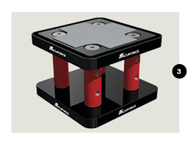
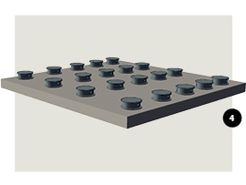
Fig 3 shows a typical vacuum “pod”. These are normally used in groups (Fig 4) to hold down large pieces of aluminum or other non-ferrous materials such as wood or natural stone, where magnets wouldn’t work, of course. A vacuum pump or vacuum venturi is connected to the side of the vacuum pod. The vacuum port is within an O ring seal. The base, which can be held onto the machine table via another vacuum port is sometimes mechanically clamped to the machine table surface. In processes where the work piece is continuously changing in size, a vacuum base connection is preferable so that it can be easily released and moved about the table.
 Sometimes vacuum pods aren’t suitable, such as in applications where the sheets being machined are very thin and therefore the sheet could “sag” between the pods. Also, if the part being machined has a profile and therefore is not flat, a custom vacuum bed would have to be made in order to match the profile of the mating face of the work piece. Fig 5 illustrates a profile vacuum bed with the work piece installed. An O-ring seal would be installed on the tool inside a groove which follows the profile of the tool/work piece face. A single vacuum pump or venturi would be connected to the tool to generate sufficient vacuum hold down force.
A less elaborate tool is sometimes used utilizing vacuum cups. 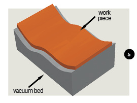 Fig 6 shows a vacuum tool which has numerous single bellows cups connected to a common vacuum source. These bellows vacuum cups protrude slightly from the tool surface so that when vacuum is applied, the cups retract, pulling the work piece against the tool face (datum surface). This type of tool can be easily put together by most end user machine shops, using readily available standard vacuum components.
Speaking of vacuum components, an end user may employ a vacuum pump or air powered vacuum venturi with vacuum pods and vacuum clamping equipment where the pump or venturi runs continuously throughout long production cycles. This would be necessary if the part being held down was porous and/or the machinery utilized a porous MDF bed as previously described. However, when holding down non-porous products, such as aluminum billets, the vacuum should and can be turned off once a safe vacuum level has been achieved. This offers a considerable energy savings, particularly if the cycle time between batch runs is extensive.
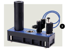
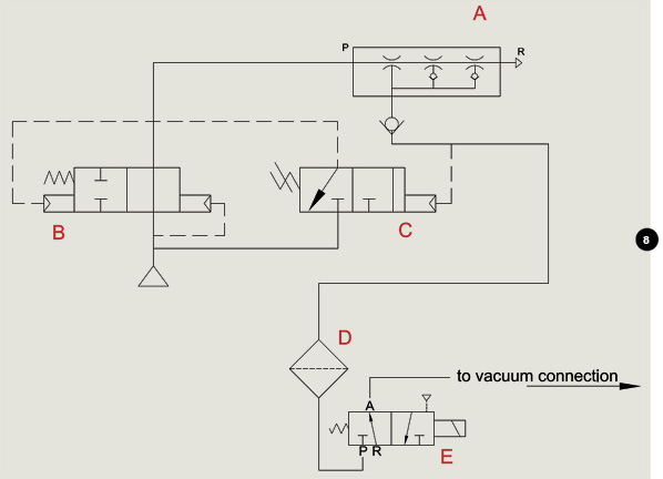
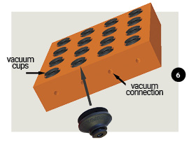 Fig 7 shows a multi-stage, air-powered vacuum generator, but it also includes what is sometimes referred to as an energy savings “kit”. This pneumatic circuitry controls the compressed air inlet to the venturi via a pilot operated 2-way valve, which is turned on and off by a vacuum sensor that has a pneumatic output. This circuit is shown in Fig 8, where the venturi (A) is powered by a pilot operated control valve (B) which is turned on and off by a pneumatic vacuum switch (C). The switch takes its vacuum reading from the vacuum port of the venturi, which is connected via a suitable vacuum inlet filter to an external control valve (E).
Therefore, the user is turning vacuum on and off to the vacuum tool with the 3-way manual valve or an automated 3-way solenoid valve (Fig 8, E). This enables considerable air savings and should always be considered as a very viable feature of any vacuum clamping application.
 If a vacuum pump is being used, an energy-saving system can be employed to cycle the pump on and off as the vacuum level rises and falls. A large vacuum vessel is also recommended as a safety measure but also helps with vacuum pump installations, where the pump will cycle on and off less often, minimizing wear and tear on the mechanical components of the pump and motor.
Vacuum clamping applications are all different but share the same end-user concerns of efficiency in production, ease-of-use and ongoing operating costs. If consideration is given to the effectiveness of the vacuum tool performance, as well as to understanding of best energy savings practice, the final solution should be an easy choice. The aforementioned examples offer an insight into effective solutions for the large majority of vacuum clamping applications in use today.
Daniel Pascoe is President of Davasol Inc, an independent industrial consultant specializing in online brand presence and industrial e-commerce stores, with clients across North America and Europe, one of which is Vacuforce LLC (www.vacuforce.com) a manufacturer and distributor of vacuum components for whom this article was co-written with.
Daniel can be reached via www.davasol.com or directly at dpascoe@davasol.com. Find Vacuforce on twitter.com/vacuforce
Share this information.
Related Posts


Sponsor

Sponsors