Hydraulic Proportional Valve Advancements
By Alan McCay, CFPS, Motion Industries
The Journal is celebrating a 25-year milestone in 2019 and reflecting on how far the industry has come since the birth of the magazine. This new column is dedicated to showcasing the growth of fluid power technology. Each article features a product or industry analysis and how it has transformed from its early years. If you have a product or analysis to share with the Journal readers, please contact Candace Nicholson at cnicholson@fluidpowerjournal.com.
There have been a lot of changes and advancements throughout the years with hydraulic directional valves. The most basic directional valve shifts an actuator from point to point at fixed speed with no acceleration control. However, newer valve technology can control accurate positioning, velocity, acceleration, deceleration, and force. The most advanced control valves have on-board electronics, which can be configured using software developed by the manufacturer to control and program a variety of parameters.
Starting with the basics, many original hydraulic systems controlling the direction and speed of hydraulic actuators simply used on/off control and manually adjustable flow control valves. This setup requires an electrical signal, typically 110VAC or 24VDC, applied to a solenoid which electromagnetically shifts a spool to a fully open position. For speed control, the engineer would need to use manually set flow controls. The accuracy of these flow controls is low, and this type of system didn’t address acceleration and deceleration of an actuator. The accuracy of flow controls did, however, improve with the development of pressure compensated flow controls that addressed speed changes caused by varying loads.
The next generation of direction and flow control used the concept of varying the electrical signal to a solenoid valve. A variable current was applied through a valve coil to shift a spool against an opposing spring. The more current present, the stronger the shifting force and more spool travel. This allowed for flow control and directional control in the same valve. Valves using a variable control signal became known as proportional directional valves.
Varying current can be achieved by using a constant 24VDC and variable resistor. However, a better method of doing this is to use a series of very fast 24VDC pulses (1 kHz typical) to the coil. The longer the on-time of the pulses, the higher the average voltage and current to the valve. Varying the pulse on-time voltage can be used to shift the spool to variable positions, therefore varying flow through the valve. This concept is called Pulse Width Modulation (PWM) and is more energy-efficient and creates less heat than using a constant 24VDC signal and resistor.
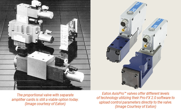
PWM technology was originally utilized with a separate amplifier card. However, the more modern versions of this include amplifier electronics built into the valve itself. The amplifiers in both versions of these valves typically use a variable 0 to 10 volt, or 4 to 20 mA input signal to drive the PWM 24VDC signal to the valve. These signals are varied throughout their range creating variable flow and directional control from one valve. No need for line mounted flow control valves. This also allows for acceleration and deceleration of the actuator by choosing how fast the signal is ramped.
The latest in proportional valve technology takes the same technology of standard on-board electronic proportional valves to a valve with electronics that are on-board and configurable. Eaton AxisPro™ valves offer different levels of technology utilizing their Pro-FX 2.0 software to upload control parameters directly to the valve.
The most basic version consists of a servo performance valve that can be configured to accept 0 to 10-volt signals or 4 to 20 mA signals, as well as other control signals simply by selecting the parameter in the software. This reduces inventory and lead times. There are also configurable options to control drive position, drive speed, and drive force control.
More complex versions of the Eaton AxisPro valves include CAN bus communication to reduce wiring and improve diagnostic options. There are also versions that have pressure sensors in all four ports and temperature options available as well. These sensors can be used for both control functions and/or diagnostics.
Even though technological advancements have been made through the years, design engineers nevertheless still have the need for the older more basic technology. Although we could use high tech options in many different applications, cost many times outweighs the need for more complex control.
Alan McCay, CFPS, has worked for Motion Industries for 24 years supporting the fluid power sales efforts, and is currently Product Sales Manager for Fluid Power. For more information, visit MotionIndustries.com/FPJournal, the Mi Fluid Power Shops video (https://tinyurl.com/yd87yble) and MiHow2 videos on Fluid Power (https://tinyurl.com/ybn2zqo3).
Share this information.
Related Posts


Sponsor

Sponsors