On Target: Meeting Cleanliness Levels with Bypass Filtration
By Mark Barnes, Senior Vice President, Global Business Development, Des-Case Corporation
Most fluid power specialists recognize the importance of hydraulic fluid cleanliness to optimize the efficiency and reliability of hydraulic systems. As much as 90% of hydraulic system problems are attributable to fluid contamination. As a result, all hydraulic system designs include filtration to meet or exceed target cleanliness levels. However, depending on the application and operating environment, meeting these targets can be problematic.
The reason lies not in the system’s design but in an inability to achieve balance in fluid contamination control. Balanced filtration is an important concept in contamination control. Put simply, balanced filtration means that the rate of contamination exclusion and removal exceeds the rate of contamination ingress. Where one achieves balanced filtration, one can expect reliable operation. Conversely, an out-of-balance system virtually guarantees poor reliability.
So how do we know if a system is in balance? The answer lies first in understanding how clean the system needs to be so that you can establish contamination control targets. Then measure fluid contamination either periodically through bottle sampling or in real time through inline sensors to ensure that you are meeting or exceeding required targets.
The answer to the question of optimum fluid cleanliness lies in understanding the system. While a low-pressure system featuring gear pumps and simple direction valves may be fairly impervious to contamination-induced failure, high-pressure systems in which tolerances are tight and that contain contamination-sensitive servo control valves are sensitive to even a slight amount of contamination. Table 1 shows typical recommendations for hydraulic fluid cleanliness based on system components and operating pressures.
Achieving target cleanliness levels
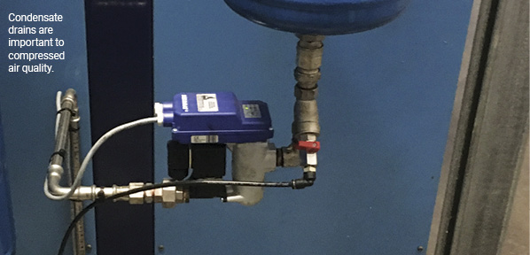
To achieve optimum fluid cleanliness, you must evaluate and address all sources of contamination. These steps include prefiltering all new fluids prior to use, installing desiccant breathers to exclude particles and moisture, and practicing good overall maintenance, such as system flushing and cleaning new hoses prior to installation.
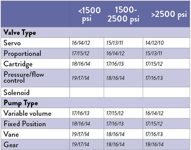
Table 1: Typical fluid cleanliness targets for hydraulic components.
All hydraulic systems use full-flow filtration to help remove internal contamination. This includes high-pressure suction line filters between the hydraulic pump and valve block and often return line filtration to eliminate contaminants that enter the system from
the actuators.
Choosing the correct inline filter is critical to contaminant control success. Take for example a hydraulic system operating at 3,000 psi (207 bar) that has servo-controlled valves. Based on table 1, we need to meet or exceed a fluid cleanliness level cleaner than ISO 14/12/10. However, to do so would likely require a minimum filter efficiency of β3=1,000 and possibly even β1=1,000, depending on the particle ingression rate.
This is where problems can occur. With full-flow filters, particle capture efficiency is a tradeoff between dirt removal and flow/pressure restriction. To understand the issue, consider a rather simplistic view of a filter as a mesh screen with a certain “hole” or pore size related to its micron rating (see figure 1). In this simplified view, any particle smaller than the pore size passes through, while any particle larger than the pore size becomes trapped. As particles become trapped, thereby removing them, the pressure drop across the filter increases, creating a restriction to flow. At some point, this pressure may exceed the filter bypass valve or pump relief valve setting.
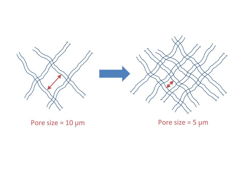
Figure 1: A simplified view of a filter as a mesh screen.
Now consider what might happen if we decide to introduce a finer mesh to capture smaller particles. Again, based on a rather simplified view of a filter, cutting the pore size in half to capture smaller particles requires, in theory, a filter area four times larger to maintain the same flow rate. As such, the filter and hence the housing or element needs to be much larger, adding cost and complexity to the system.
Of course, most hydraulic filters are more than just mesh, but the general principal applies: increasing small-particle capture efficiency may require the use of a larger filter. For this reason, it is not uncommon to see a 5-micron or even 10-micron filter used when a high-pressure system demands fluid cleanliness levels below ISO 16/14/11.
Where system design limitations prohibit the use of larger, more expensive filter elements, a good alternative is to add supplemental filtration in the form of offline filtration. Offline filtration, sometime referred to as kidney loop filtration because of the similarity to kidney dialysis, allows for finer filtration because it is not installed inline. This means that flow rates can be slower, an advantage with contamination control since the residence time of the fluid in the filter can have a big impact on capture efficiency.
While offline filtration has proven highly effective at removing contamination, it does add one layer of complexity: the need to add an additional fluid circuit, including pumps, hoses, and a filter housing. This leads to added cost and the potential for leakage and other maintenance issues.
Fortunately, you can minimize these issues with a form of offline filtration often called bypass filtration, which involves taking a small slipstream of pressurized fluid, often from a readily available pilot circuit, then returning the fluid back to the unpressurized sump (see figure 2).
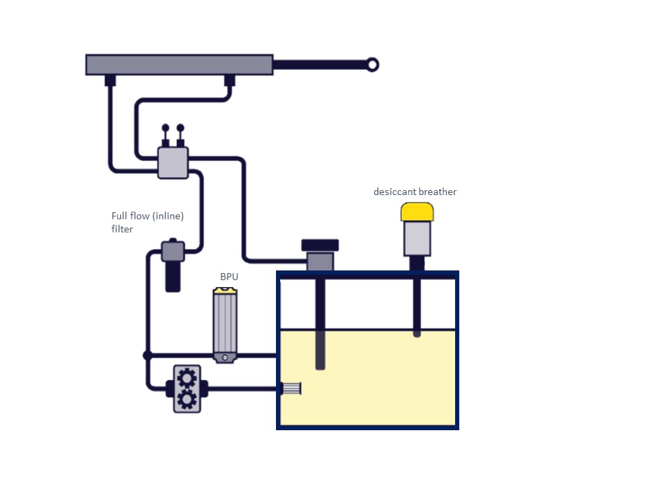
Figure 2: Installation of bypass filtration in a hydraulic system.
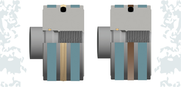
The most effective bypass filtration systems use radial depth media filtration. Unlike conventional filters in which the filter media is composed on three to seven layers of media, radial depth media elements are wound cellulose elements, which have to exceed β=2,000 at 2 microns while maintaining high dirt-holding capacity and low pressure drop (see figure 3).
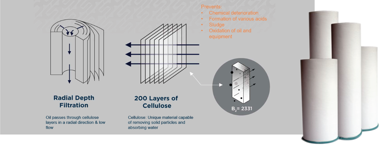
Figure 3: Radial depth media filtration.
Bypass filtration systems excel in applications with accessibility and size constraints, such as mobile and marine applications. To illustrate their effectiveness, consider the example of a marine hydraulic system aboard a tugboat (see figure 4). Used to power deck-side systems such as the anchor, cranes, and winches, the hydraulic system was designed to be small and compact due to the limited space available and a relatively low budget. Because of this, designers used a relatively small inline filter housing with a conventional 10-µm high-pressure pleated microglass filter element.
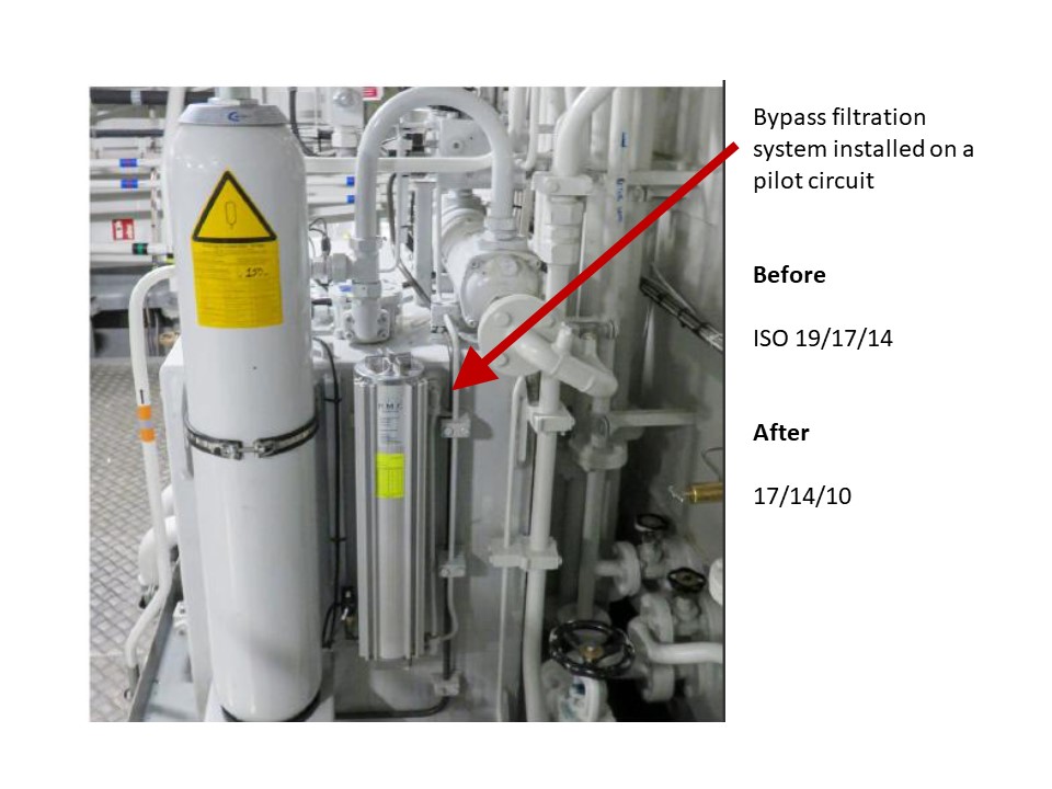
Figure 4: Bypass filtration unit deployed aboard a tugboat.
Due to the relatively low capture efficiency, hydraulic fluid system cleanliness was typically maintained at a relatively dirty ISO 19/17/14. By installing a compact bypass filtration system, fluid cleanliness levels improved to an acceptable ISO 17/14/10 without increasing the overall size of the system aboard the vessel. Because of the increased fluid cleanliness level, system reliability improved, as did oil and component life, without significant added cost.
Driven by economic and environmental demands, hydraulic systems are getting smaller, particularly for mobile and marine applications. As the hydraulic unit footprint decreases, the significance of hydraulic system cleanliness increases, creating problems with adding adequate full-flow filtration to achieve optimum target cleanliness levels. Adding offline filtration and particularly bypass filtration, which requires little more than an available pilot circuit, small housing and a compact, high-efficiency filter, offers hydraulic system designers and operators an added tool to combat contamination-induced failures.
Share this information.
Related Posts


Sponsor

Sponsors