Variable Speed Pump Drives for Industrial Machinery – System Considerations
Despite ominous predictions in the ‘80s and ‘90s, hydraulics being completely replaced by electrical drives did not occur, and fluid power still plays an important role in modern drive technology. Moreover, it is impossible to imagine many fields of industry working without hydraulic drives. The enormous power density makes hydraulic drives irreplaceable when large forces and high torques are required. Over the last 30 years, “traditional” hydraulics has evolved into electro-hydraulics, where the use of electronics and closed-loop controls has become an industrial standard. For years it was common to depict hydraulics as “strong, but stupid.” Today this reputation no longer exists; hydraulics is not only strong, but also “intelligent.” Modern fluid power drives are perfect examples of integrated mechatronic devices.
Ongoing competition with electrical drives and ever-increasing requirements of performance and energy efficiency have led the hydraulic drive industry to new and more advanced system solutions.
The power control of electro-hydraulic drives typically uses resistive or volumetric control. In resistive control, the system is controlled by a valve, usually a proportional device, to throttle oil flow delivered from a power-supply source. In volumetric control, flow is controlled by adjusting the displacement of a pump or by directly changing the drive speed of a fixed or variable displacement pump. Resistive control possesses excellent dynamic characteristics, however it exhibits poor energy efficiency. Significant power losses occur due to dissipation in the control valve. This is, in effect, hydraulic resistance.
Rising costs of energy and increased awareness of environment issues has resulted in new trends in drive systems. Over the last two decades, improving electro-hydraulic efficiency was a main goal of many companies and research institutes. Given advances in drive technology and closed-loop control, the resistive throttling method is being replaced more often by more efficient volumetric control using speed variable pump systems.
Reducing throttling losses lowers the amount of heat transferred to the oil and oil reservoir. Lower heat generation allows for a smaller-capacity cooling system and lower parasitic power needed to maintain optimum oil temperature.
Using Variable Frequency Drives (VFDs) with hydraulic power units can also lower average noise emissions, as the pump speed is reduced during partial-load operations, such as pressure holding or idling. The average sound level can be lowered by as much as 10-20 dB(A), improving environmental working conditions.
The combination of advanced electric-drive technology and hydraulics opens a new chapter in electro-hydraulic drive systems. Machine builders can now benefit from the traditional hydraulic characteristics of robustness and power density, and additionally benefit from the well-known advantages of electrical drives: inherent drive “intelligence” and ease of integration with factory automation systems.
This changing landscape of hydraulic drives pushes fluid power specialists to quickly adapt to using variable speed pump drives. For many engineers, this may not be an easy step. Optimum utilization of variable speed pump drives requires, in many cases, additional system design considerations and modifications to a hydraulic system design. Fluid power engineers need to understand the distinctive features of VFDs and the requirements of the production process being driven. This will define the critical points for the electric and hydraulic elements. The goal of the system is to meet the requirements of dynamics and accuracy, but also keep the focus on overall energy efficiency. When applying a VFD-driven pump, using a conventional induction motor or a permanent magnet servomotor (PMM), the dynamic behavior will differ from a traditional system using a constant speed pump drive and throttling control valve.
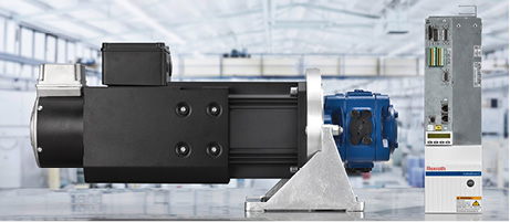
Systems using variable speed pump drives can use a number of different design solutions. The selection of the design solution depends on a number of factors. The type of hydraulic circuit, the required response times and accuracy, the power required, and other factors all come into play when deciding the best drive and circuit design. Dynamic performance and power requirements determine the choice of the motor. For applications requiring the fastest response times and highest accuracies, a PMM may be the best selection. Today this technology is used extensively in plastic injection-molding machines. These drive systems offer extremely high performance and have high productivity rates. Due to their high power density and low drive inertia, PMMs have the highest acceleration capabilities. These high dynamics allow complex machine control tasks, such as direct force, speed, and cylinder position control, to be realized without proportional valves. The main limitation when using PMMs is maximum continuous output power, typically less than 60kW. Power units with higher output power, greater than 60kW, may require multiple PMM-pump groups.
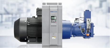
Standard asynchronous induction motors driven with VFDs can be used in higher-power applications, where direct control of high dynamic axes is not required. Using standard induction motors with VFDs, operating in a sensorless vector control mode (no separate motor feedback device required) results in a cost-effective system. However, the system designer should be aware of the limitations of direct control using these drives. The system response times can be long as a result of the high inertia of the induction motor. Variable speed pump drives using standard induction motors with VFDs are used today in the woodworking industry, on press applications, in plastics machinery, heavy industry applications, and machining tool applications where the control task is typically regulating system pressure or flow.
The motor size and drive should be selected based on the pressure-flow-time cycle (p/Q profile) for the application machine. In practice, motors on standard HPUs are often sized on “corner power,” calculated from the maximum pump pressure and flow, and duty cycle is commonly not taken into account. This results in the installation of excess motor HP. If partial load comprises a significant portion of the machine cycle, the excess motor power can be significant. Sizing PMMs for variable speed pump drives should follow methods commonly used in electro-mechanical actuator drives: calculating the root mean square (RMS) value based on the load torque and average drive speed. Once a pump size is determined, the motor torque and speed are calculated from the required pump pressure and flow. Additionally, the dynamic torque requirements for accelerating and decelerating the motor’s rotor and pump inertia need to be added. These calculated values are used to select the proper size drive and motor. Drive sizing and system optimization can be done using specialized tools, such as Bosch Rexroth’s SytronixSize, which allows analyzing p/Q profiles and motor load factors. For a more complex analysis, a numerical simulation can be used to model the system. Dynamic simulations help by providing more insight to the system dynamics, such as pressurization dynamics, and to investigate interactions between the drive and the hydraulic system. Analysis of the performance of closed-loop controls can be done, as well. These dynamic simulations can be carried out using software that includes drive and hydraulics model libraries. Simulation tools, such as Bosch Rexroth’s Simster 3, ITI SimulationX, or MATLAB/Simulink Simscape can be used for these requirements.
When selecting the pump for variable speed operation, several important factors must be considered:
- Is the pump construction suitable for variable speed operation?
- What are the minimum and maximum allowed RPM for the pump?
- Can the pump be used bi-directionally, and if so, are there any pressure and speed limitations?
- Is the pump suitable for start and stop operation?
- What is the maximum operating pressure allowed for the pump, and does pressure affect the maximum allowable pump speed?
- What fluid will be used in the system, and does it limit the pump’s pressure and speed based on viscosity and pump lubrication?
- What is the mechanical and volumetric efficiency of the pump at the design operating points?
- What are pump acoustic noise level considerations, based on expected speed, pressure, and displacement?
- What will the pressure and flow pulsations be over the range of operating speeds?
- Is the hydraulic circuit of open or closed type?
Improper pump selection or operation outside allowed conditions can result in premature pump failure or suboptimal control performance.
Pumps used with speed variable drives typically are internal gear or piston pumps. In some cases, properly selected vane pumps may also be used.
Internal gear pumps are characterized by high efficiency, low flow ripple, low mechanical inertia, and high-pressure capability. Due to these characteristics, they are widely used with PMMs on injection-molding machines. The limitations are fixed displacement and limits on the minimum drive speed during pressure-holding operation. Axial piston pumps, either fixed or variable displacement design, have desired properties of high efficiency at low speed, making them ideal for pressure-holding operation. Using a variable displacement pump allows the possibility to lower the motor torque during pressure holding in the machine cycle. This can result in higher system efficiency, since the motor and pump can operate under more desirable operating conditions. Using a high-response variable displacement pump with closed-loop displacement control, such as Rexroth’s DFEn 5000, the pump’s performance can compensate for relatively low dynamics of the VFD drive and motor. The pump displacement control can react a magnitude or more faster than the motor speed control. This is of greater value when used with higher HP drive motors.
It is expected that speed variable pump drives will replace an increasing number of standard motors in hydraulic power units in the future. This change is already utilized by many plastic machinery OEMs and is quickly expanding in press applications. Understanding the principles of variable speed drives and the interaction between hydraulics and electric drives will be key to future fluid power engineering.
by Jan Komsta, Ph.D., and Paul Stavrou, Bosch Rexroth. For more information: This article is based on a presentation at the 2013 Fluid Power Systems Conference held in Rosemont, Ill., from November 19-21, 2013. Jan Komsta, Ph.D., is manager of new technologies, and Paul Stavrou is technology manager for Bosch Rexroth. Visit www.boschrexroth-us.com.
Share this information.
Related Posts


2 thoughts on “Variable Speed Pump Drives for Industrial Machinery – System Considerations”
Leave a Reply
Sponsor

Sponsors
Good hydraulic pump draw high power, so does top ANSON’s hydraulic pump end in reputed products. What lead us are our guiding words, ” Technology upgrading, quality insistence, comprehensive service. Based on this faith, we are always dedicated to R&D. We had invested in the most advance CNC profile grinding machine imported from JAPAN, which created the top performance of ANSON’s hydraulic pump.
Thanks a lot for sharing this with all of us. Bookmarked.