Take Measures: 10 Tips For Sizing Rodless Pneumatic Actuators
 By Andrew Zaske, Vice President, Sales and Marketing, Tolomatic Inc.
There are many important points to consider when sizing rodless pneumatic cylinders. Some are relatively simple procedures, such as knowing available air pressure and determining the proper working stroke and overall length. Others can be more complex, such as determining the effects of moment loads, dynamic loading, and breakaway pressure. Manufacturers’ sizing and selection calculations can make it easier to select the appropriate cylinder. Here are 10 tips to help make the most accurate selection.
1 Obtain an accurate air-pressure reading.
Overestimating or underestimating the available air pressure can cause a loss in actuator performance or possibly a complete malfunction. To obtain an accurate reading and build in safe engineering practices, check the air pressure with a gauge. For example, a plant may supply 100 psi of pressure. However, pressure can fluctuate as much as 10% at different locations in the plant due to variable demand cycles. This means the actual available air pressure is only 90 psi.
A 5% to 10% fluctuation in air pressure is quite common and can make a big difference in selecting the proper cylinder for an application. It is always best to factor in a 10% loss from the gauge air pressure.
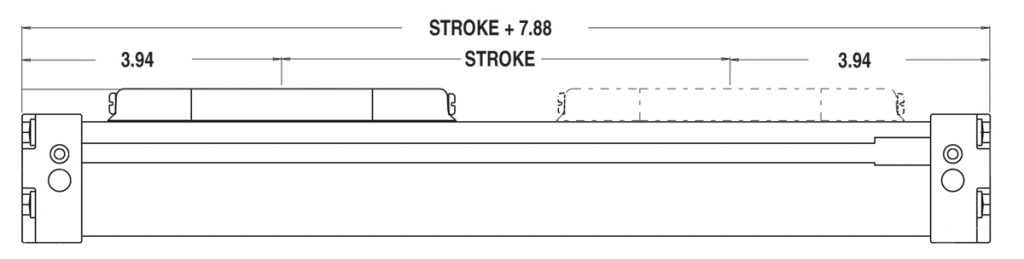
2 Calculate the actuator’s working stroke and overall length.
An actuator’s “dead length” is the portion of the actuator stroke that cannot be used due to the interference of the internal components and the room needed to physically come to the end of stroke. This dead length is determined by the manufacturer and should be indicated on the dimensional information for each actuator.
The actuator’s overall length is the sum of the distance of travel (working stroke) and the given dead length at each end of the actuator. Auxiliary carriers and other actuator options will also add to the actuator’s dead length. For example, for a cylinder with two carriers, add the total dead length, working stroke, and the distance between the center of carriers to determine the cylinder’s overall length. It is important to reference the dimensional information provided by the manufacturer when ordering options to properly determine if additional dead length is required.
In the illustration below, the nonworking (dead) space required by the mounting and carrier mechanisms is defined as 3.94 inches at each end of the actuator. In this case, the actuator requires 7.88 inches of total dead space. Add this dead space to the desired working stroke requirement to determine the overall actuator length. In this example, the actuator needs to have a working stroke of 16.12 inches. To determine the overall length, add the working stroke (distance of travel) and the total dead length: working stroke (16.12 inches) + total dead length (7.88 inches) = overall length (24 inches).
3 Size the cylinder accurately.
When it comes to cylinder sizing, bigger is not necessarily better. Oversizing can cost more in money and air consumption. On the other hand, undersizing a cylinder may save a few dollars, but it will not provide optimal application performance or the appropriate operational safety factors. For optimal performance, size the actuator based on load, force, and bending moment performance capacities with a safety margin factor.
To properly size a cylinder, you need to know these application requirements:
• Available air pressure
• Magnitude of load
• Orientation of load (location relative to cylinder carrier)
• Final velocity of mass attached to carrier
• Working stroke length
• Cycle rate
• Cycle time
• Center of gravity of load in relation to the cylinder’s load carrying device
• Orientation of the actuator
Once you know these factors, then determine the cylinder’s load (thrust) force capacity based on the indicated available air pressure. The
cylinder should perform within the specified
capacity range. If the application requires performance at the maximum level for that cylinder, consider either a larger bore size or a different cylinder style with higher capabilities.
After selecting the bore size, calculate the magnitude and orientation of the load. Often, a cylinder is selected based only on the force it can produce. If the actuator will also support a load, it is important to know the bending moment capacity of the cylinder’s bearing and load carrying system. This will determine if the cylinder is capable of performing consistently under the load requirements. Also, when determining the force requirements, consider dynamic moment loading, discussed in tip 5. Selecting the wrong cylinder can result in poor performance, reduced life, excessive component wear, and cylinder failure.
4 Know the effect of resulting moments (torques).
The position and size of the load on the cylinder determines the resulting bending moments applied to the cylinder itself. Even if a load is located on and directly over the center of the load carrying device, it will still be subjected to bending moments on acceleration. It is important to determine if the cylinder is capable of handling the resulting moments. For off-center or side loads, determine the distance from the center of mass of the load being carried to the center of the cylinder’s load carrying device and calculate the resulting bending moment. For example: Distance of center of mass of the load from the center of the cylinder’s load carrying device = 3 inches. Load being carried is 30 pounds. My = 3 inches x 30 lbs = 90 in-lbs.
5 Calculate the effects of dynamic moment loading.
Unlike rod-style cylinders, many rodless cylinders must support the load during acceleration and deceleration at each end of stroke. When there are side or overhung loads, calculate the dynamic moments to determine which rodless cylinder is best equipped to handle the resulting forces.
6 Understand the importance between average and impact velocity.
Velocity calculations for all rodless cylinders must differentiate between average velocity and impact velocity. For example: Stroking a 24-inch actuator in 1 second yields an average velocity of 24 inches per second. To properly determine the inertial forces for cushioning, it is important to know the final or impact velocity.
A guideline for determining the final (impact) velocity is: 2 x the average velocity (2 x 24 in/sec = 48 in/sec impact velocity).
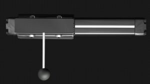
Moment Directions
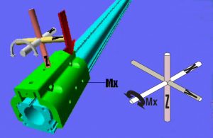
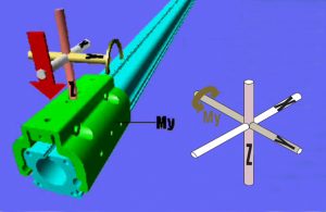
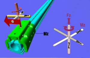
MX, MY, and MZ moments are created by loads applied at a distance from the respective X, Y, or Z axes. An example is an overhung load that is centered off to the side of the cylinder’s load carrying device. MX moments create a rotation around the X axis, and the red arrow indicates the direction of the resulting “roll” motion on the cylinder’s carrier and bearing system. MY and MZ moments likewise create rotation around the respective Y and Z axes. The resulting “pitch” and “yaw” motions are shown by red arrows.
The farther away the load is from the center of the cylinder’s load carrying device, the larger the resulting moment.
Published bending moments are usually a maximum and assume only one type of moment is being applied. Some applications involve two or more of the moments described above. Evaluate each application and calculate per the manufacturer’s equation to determine if the cylinder is capable of the combined moment force.
Dynamic Loading
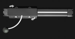
The illustrations below, viewed from the top of the cylinder, show the effects of dynamic loading to the cylinder and its load carrying device. This condition occurs at deceleration (end of stroke) and acceleration (beginning of stroke.)
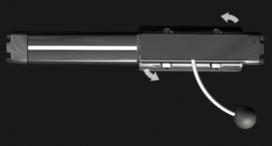
In the first illustration, the ball represents an overhung side load exerting an MX moment on the cylinder’s carrier.
The second illustration shows what happens when the cylinder reaches one end of its stroke. When the carrier stops, inertia keeps the load moving forward, creating a dynamic twisting moment (MZ) on the cylinder.
The same thing happens when the cylinder cycles to the other end of stroke. The resulting dynamic moment may exceed the rated capacity of the actuator. After repeated cycles, the actuator may not achieve its designed life expectations if not properly selected.
Shock absorbers (mounted on the cylinder) are normally used in such applications to help compensate for the inertial effects of dynamic loading. In addition, place a stopping device nearest to the center of gravity of the moving load. For more information on this topic, see tip 7.
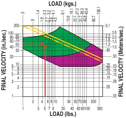
7 Calculate the cushion or shock absorber
capacity.
Most rodless actuators are equipped with internal devices to help cushion the load
at end of stroke. It is important to know the final or impact velocity to determine the cylinder’s cushioning capacities. In the graph on the right, the final velocity has been determined to be 50 inches per second, and the load being moved is 5 pounds. The intersection of these two points indicates that the level is within the cylinder’s cushion capacity, which is indicated by the yellow lines. Consideration now must be given to load position and the resulting moments exerted on the cylinder, (refer to static and dynamic moments in tips 4 and 5) to determine if shock absorbers or external load stopping devices are required.
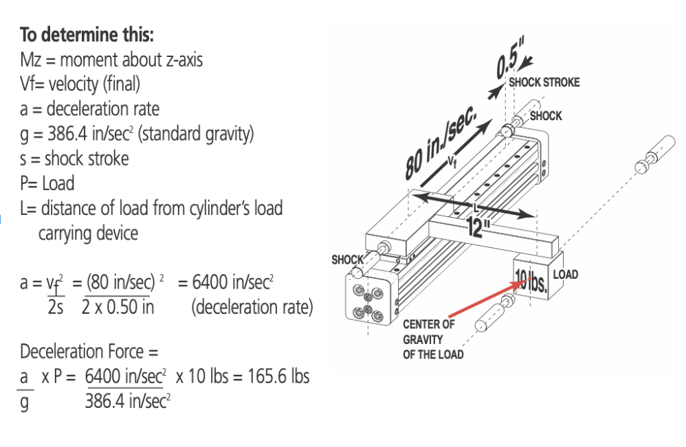
In the illustration below, the cylinder is carrying a 10-pound load and traveling at a final velocity of 80 inches per second when coming in contact with the shock absorber located at the ends of the cylinder stroke. The load must be stopped within the shock absorber stroke of 0.50 inches. The Mz and equivalent force applied to the cylinder’s load carrying device need to be within the limits of the cylinder’s rating capacities.
If the final velocity cannot be accurately determined, consider using limit switches with valve deceleration circuits or shock absorbers.
8 Factor in the effects of motion lag due to breakaway, acceleration, and friction forces.
It is important to understand how other forces and losses affect the total force required to produce the desired motion. The total force calculation considering all sources of forces and frictional losses is:
Ft (total force) = Fa (acceleration force) + Ffr (forces due to friction) + Fbk (breakaway force)
Breakaway force. Every rodless cylinder requires a certain amount of energy or force to move itself with no load attached. This is the breakaway force. When reviewing the performance information for the cylinder, be sure that breakaway force is
accounted for in the calculations. In pneumatic applications, it is best to have excess force available to achieve reasonable acceleration.
Acceleration force. The amount of force required to accelerate a mass is typically larger than the force required to keep the load in motion. When selecting an actuator, add the breakaway force of the cylinder and the frictional drag of the load to the acceleration force requirements.
Friction forces. Friction forces occur when two materials slide across each other’s surface. The level of friction present between the two materials is defined by a numeric value called the coefficient of friction (COF), which varies depending on the material, the surfaces with which it comes in contact, and the type of friction (sliding or rolling) being generated. Engineering reference tables should be used to determine the COF for materials and surfaces used for specific applications.
For horizontal applications, to determine the force required to overcome the friction, multiply the mass (weight) of the load by the COF:
Ffr (forces due to friction) = μ (coefficient of friction) x WL (weight of load)
9 Size for vertical vs. horizontal applications.
There are additional force, load, and air considerations when a cylinder is mounted vertically in an application. A vertically mounted cylinder must also overcome the force of gravity before it can accelerate the load upward.
In addition, certain types of pneumatic rodless actuators may experience some degree of air leakage. If the actuator is required to hold a load vertically for any length of time, the amount of air leakage can affect how well that position can be maintained.
In certain circumstances, some other type of holding device (such as a brake) or external guidance system may be required to safely control the load. Vertical applications with externally guided loads still experience moment loads due to the effect of gravity. For example, a 50-pound load with a bracket arm 12 inches from the actuator’s load carrying device would be subjected to a 600 in-lbs moment load.
10 Know environmental conditions.
Extremely hot or cold temperatures, external abrasives, dirty or wet conditions, caustic fluids, and air quality are just a few of the environmental conditions that can affect cylinder life. The effects of friction wear (abrasive, pitting, adhesive, and corrosive) due to particulates or fluids coming in contact with the cylinder can cause premature wear, increased maintenance, and possible equipment failure.
Most manufacturers specify a cylinder’s performance based on normal operating conditions. If the cylinder is to be operated in adverse environmental situations, discuss the application with the manufacturer to determine if the cylinder is capable of delivering the expected performance.
Determining the right pneumatic rodless product can be an in-depth process because there are many different styles to consider. But in many applications, the space-saving feature and integral load-bearing system of rodless cylinders make them an ideal choice for linear motion. Consulting with an experienced manufacturer improves the selection process. The result: long life and trouble-free cylinder performance.
Share this information.
Related Posts
Don’t Follow The Crowd, Mount Your Hydraulic Pumps…For Life

Torque Division & Speed Synchronization Using 1:1 Counterbalances
An Introduction to Hydro-Mechanical Transmissions

Creating a Safer Workplace With a Few Simple Hose Management Changes
Checked: Avoiding Hydraulic Hose Disasters
Air Actuators Win Over Users with Durability and Long Service Life
Sponsor

Sponsors