The Basics of Variable-Displacement Pump Controls
 If you are operating a vane or gear pump, in most cases the controls are fairly simple. The pump is either loaded (doing work) or unloaded (all flow going back to the reservoir). These are primarily fixed-displacement devices, so the amount of flow is only based on the input RPM; otherwise, the flow remains constant. This is referred to as an open-loop system. After doing the work, the flow is open back to the tank. In a closed-loop system, after doing the work, the flow is returned to the pump. Closed-circuit pumps offer additional, but different, control options.
Open-Loop, Variable-Displacement Piston Pumps
Variable-displacement piston pumps offer an array of controls based on pressure, flow, HP, or a combination of all of these. I’ll run through the basic types and reasons that you would use each.
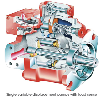
One concept, which needs to be explained first, is the variable displacement. The amount of flow that each pump can provide is dependent on a rotating group of pistons. By varying the stroke of the pistons, we adjust the displacement of the pump. In a variable-displacement pump, we vary the angle of the rotating group, which is done by tilting the swash plate.
Pressure-Compensation—Reduced Flow After Reaching Set Pressure
Pressure-compensated control is the most basic control for a variable-stroke piston pump. The swash plate of the pump is off-set by a heavy spring and an internal piston, holding the pump at maximum displacement. When the prime mover (an electric motor or another device) turns the pump shaft, the pump will produce maximum flow. The system pressure pushes back against the the internal piston, which is being held by the heavy spring. When the force of the system pressure is high enough to move the piston and overcome the spring pressure, the swash plate angle is lowered and the pump flow is reduced. As the load varies, the system pressure changes, which alters the angle of the swash plate. The pump will produce just enough flow to maintain the set pressure.
This is a very simple control method, and in certain applications, this is all you need. You can adjust the spring tension, but that’s it. Remember, the flow of the pump is not adjusted until you have built pressure at full displacement. You must have enough HP to take the pump to full pressure at full flow. If there is not enough HP, the prime mover will slow down or stall before the pressure begins to compensate and lower the flow.
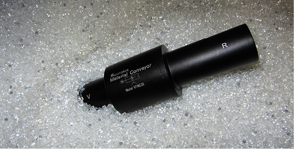
An application example is using a hydraulic motor to operate a conveyor. The load is constant, and the motor requires about 1500 psi to handle the load. You set the piston pump compensator at 1600 psi and let it run. Your system will also need a safety relief in case of emergency. System pressure is adjusted using the pump compensator, and the system relief should be set a few hundred PSI higher than the pump compensator. If they are set too close, they can fight each other, causing the pump to go on and off stroke and/or the relief to open and close, causing inefficiency, heat, and vibration.
Load Sense—Let the Load Determine the Flow
 Another option is to utilize a load-sense compensator, which includes a lighter spring setting to control the swash plate. Upstream pressure is ported into a load-sense port on the pump. As the pressure requirement increases, the pressure acts against the load-sense piston. Once the pressure requirement is higher than the offset, the pump swash plate angle changes and the pump begins to increase flow by increasing the swash plate angle until we have enough pressure to balance the piston. Once balanced, the flow remains steady until the load changes. With a load-sense compensator, the pump produces flow at load pressure plus the spring offset, which is normally 200-300 psi.
This system will also utilize a standard compensator, so if the system pressure increases enough, the pressure compensator will take control and reduce the swash plate angle to reduce the pressure.
Let’s look at my initial application, but this time, it has a varying load. The conveyor requires 1500 psi to move 50% of the time, but the balance of the time, the system requires between 2250-2500 psi to move the load. With a standard pressure compensator, you would have to set the pump at 2600 psi to accomplish the work. When the work only requires 1500 psi, the pump will be trying to produce 2600 psi. Fifty percent of the time, your system will be operating at 1100 psi of inefficiency, which means heat. With a load-sense compensator, when the load requires 1500 psi, the pump will actually produce about 1700-1800 psi. Yes, this is 300-psi inefficient, but that is much better than 1100-psi inefficient.
Flow Control—Adjust Load Sense with a Proportional Throttle
With a varying load, the load sense is a much better system. For additional control, you can utilize an electronic proportional flow control or throttle. You can use an electrical signal to vary the hydraulic signal, which is received by the pump’s load-sense line. This would give you full electronic control of the amount of flow the pump produces.
There are additional control options that allow you to remotely control the pressure compensator. With this remote compensator control, you can set two or more different system pressures. With the ability of a variable-piston pump to build 5000 or more PSI, the additional setting can be used when operating components with a much lower pressure requirement.
HP Control—Maximize HP Utilization
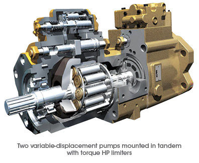
The next control is a torque-limiting or HP-limiting control. By adding an additional spring and piston, you can set a pump to always maximize its allowable input torque, therefore maximizing output flow and pressure at a defined setting.
This gets a bit more complicated, but here is an example to demonstrate how the control works. In this application, you are operating a cylinder with a 10″ bore and 150″ stroke. During most of the stroke, the cylinder is not doing very much work and can operate at 800-1200 psi. During the last 20″ of stroke, we want to hit our system pressure of 4500 psi, but we can move much slower.
Our pump has an output of 15 CIR, a maximum flow of about 113 gallons at 1750 rpm. Our prime mover is an electric motor, 75 hp with a 1.15 service factor. I want to keep my cylinder moving as fast as possible, but I want to ensure that I never exceed a power demand of 82 hp.
At 82 hp, the pump can produce its full output of 113 gpm at 1254 psi. As the load requires more pressure, the pump will begin to reduce flow and increase pressure. At 1560 psi, the system will produce about 90 gpm; at 2350 psi, we can get almost 60 gpm. At 4500 psi, the pump flow will be reduced to about 31 gpm. The advantage of this pump is that the internal controls of the pump are adjusting to maximize flow and pressure at all times without exceeding the available HP.
If I wanted to use a pump that could produce 113 gallons of flow at 4500 psi, I would need 296 hp. If I choose a 75-hp motor with a pressure-compensated variable-piston pump, the motor would stall before the pressure compensator could kick in and reduce the pump flow. Depending on the load, a load-sense pump could also stall the 75-hp motor if the load pressure is high enough to use up the HP before the pressure compensator kicks in. With a torque-limiting (HP) control, we utilize the full limits of the prime mover and maximize power usage.
When beginning to work on a new application, call a certified hydraulic or fluid power specialist to help you pick the correct pump for the job.
About the author: Paul Badowski, CFPPS, CFPHS, CFPS, has been an account manager in the fluid power industry for over 25 years, calling Michigan, Florida, and now Georgia home. His background includes pneumatic, electrical automation, and hydraulic systems and components. Mr. Badowski has been working with Cross Company – Mobile Hydraulics & Control Systems Group for over 16 years. He can be reached at paul.badowski@crossco.com.
Share this information.
Related Posts

The Do’s & Don’ts of High-Pressure Hose Care and Use

Is It Time to Rethink Open Loop Hydraulics in Agriculture Machines?
Product Focus: Clean Seal System
Fluid Power Professional Publishes Historical Fluid Power Book
Basic Vacuum Conveying
How Do You Know When You’re Ready for Electro-Hydraulic Implementation?
One thought on “The Basics of Variable-Displacement Pump Controls”
Leave a Reply
Sponsor

Sponsors
Hydraulic pump for a mittisubi K4M 1.995 litter engine. It’s an engine mounted hydraulic pump.