Basic Vacuum Conveying
There exist many different methods of conveying product with vacuum. Some are very elaborate, and indeed, some are very expensive. The conveyance of material in a production environment is very common and widespread in industries such as food, pharmaceuticals, and plastics. This article focuses on point-of-use conveyors that are very common in basic conveyance of granular type products such as grain, plastic pellets, paper streams, and so on.
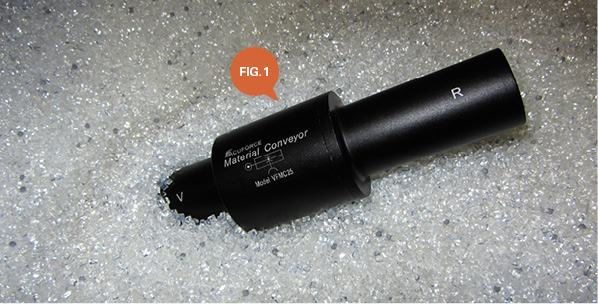
Fig. 1 shows a typical material conveyor. Powered by compressed air, these simple devices offer the user a quick and powerful method of vacuum conveyance.
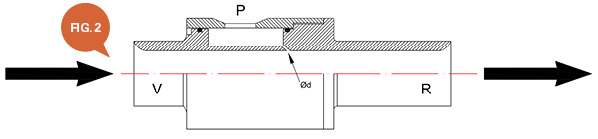
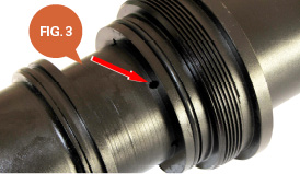
As shown in Fig. 2, the compressed air is attached to the center of the unit at port “P.” The compressed air flows into an annular ring and is forced through small angled orifices. This is shown as “Ød” in Fig. 2 and highlighted in Fig. 3, which is an internal picture of the same model shown in Fig. 1. This air flows towards port “R,” which is the exhaust. A vacuum force is created at the inlet (port “V”), where the product, such as plastic granules, is pulled into the unit. As the media passes through the unit, it is pushed out of the exhaust (R) into a receiving hose and transported to the intended destination.
This type of single-stage venturi (material conveyor) offers a compressed air to exhaust ratio of about 1:4. This means that if the unit uses 25 cfm of compressed air, it will generate 100 cfm of exhaust air at a lower pressure.
The vacuum hose is pushed over the “V” port diameter, and the exhaust hose is pushed over the “R” port diameter. This type of conveyor is available from various manufacturers, and normal internal bore sizes range from Ø1/2″ to Ø2″ ID. One of the biggest advantages of this type of conveyor is that it is maintenance-free, and no moving makes them an ideal solution for mold tool granular product conveyance, machine swarf clean-out, hopper filling of small parts, paper stream clearance from slitting machines, and so on.
 These types of vacuum venturi, because of their ratio of compressed air versus exhaust flow, can also be used for fume extraction, flow amplification in air-cooling applications, and also sheet separation in the printing industry where normal compressed air is often used, which is very expensive.
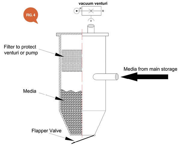
However if the conveying application is a continuous operation, the compressed air consumption of these models can be quite high. Therefore, more elaborate systems such as the one shown in Fig. 4 can be used that offer a two-stage operation. The top half of the cylinder generates vacuum that “pulls” in the media, which under gravity falls to the bottom. When the internal level switch indicates the lower tank is full, the vacuum generator is turned off, the chamber is brought back to an atmospheric condition (vacuum is vented), and a flapper valve at the base of the chamber opens, allowing the media to fall into a receiving vessel.
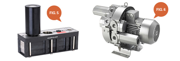
With this type of conveyor, a high vacuum level can be generated, which means a potentially longer conveying distance. Also, a multi-stage compressed air vacuum generator (Fig. 5) can be used, which uses less compressed air or even a regenerative blower such as the model shown in Fig. 6. These types of installations are popular where continuous batch conveying is required for larger machinery and are often seen in food processing and pharmaceutical operations.
Vacuum conveying offers very obvious advantages over mechanical product transfer, such as belt conveyors. The two types of vacuum-conveying methods shown here offer a basic insight into the technology employed in many types of industries. There are companies that specialize purely in pneumatic or vacuum conveying with installations that involve huge silos being placed outside of the building because of the sheer volume of media that requires transportation. The media itself has a large influence on the type of vacuum conveyance products used, based on its specific gravity and surface area. It’s a lot easier to blow a piece of 1/8″ diameter plastic bead through a hole than it is to do the same with a steel ball of similar dimensions.
This article is intended as a general guide and as with any industrial application involving machinery choice, independent professional advice should be sought to ensure correct selection and installation.
By Daniel Pascoe, Davasol Inc.
Vacuforce LLC is a manufacturer and distributor of vacuum components and systems for industry in North America. Vacuforce can be reached via its website (www.vacuforce.com) or directly at sales@vacuforce.com.Illustrations and 3D models supplied by Daniel Pascoe at Davasol Inc., an industrial distribution branding company. Daniel can be reached at dpascoe@davasol.com.
Share this information.
Related Posts


Sponsor

Sponsors