The Vacuum Cup Holds the Key
By Dane Spivak, Engineering Manager, Davasol Inc.
There are countless types of vacuum cup models in existence, and choosing the right one for an application has never been more difficult. The selection process can be overwhelming to say the least. With so many options that can get the job done, what is the best way to determine the ideal fit? It helps to understand the features of a vacuum cup and the purpose behind the designs.
The gripping force generated by vacuum is solely dependent on the pressure over the area, which is the definition of an applied force. Given that most cups are round, this translates to the diameter and vacuum level being the criteria related to the gripping force. Manufacturers usually advertise vacuum cup diameters as the maximum outside diameter (OD) of the cup. However, when a vacuum cup seals against a surface, the diameter of the applied pressure region is often smaller because the cup lip requires space to generate the seal. Other features may further reduce the area of pressure. The actual area under vacuum pressure is referred to as the effective area. Figure 1 illustrates an example of gripping forces using the OD measurement versus the effective gripping area diameter.
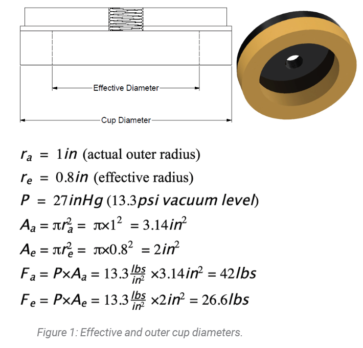
The difference in the measured area based on the OD versus effective area varies with the cup model and how it seals. Some manufacturers publish this data while others rely on built-in safety factors during the system-design process. Luckily, safety factors in vacuum are usually substantial. Lifting forces in data sheets may vary depending on the use of effective area, vacuum levels, safety factors, and other aspects considered by the manufacturer. It is important to understand how the lifting force numbers are finalized. However, by the laws of physics, cups with the same effective area offer the same vacuum gripping forces.
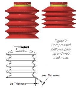 The bellows of vacuum cups are often used to describe cups since they are a prominent visual feature. Figure 2 illustrates a multiple-bellows cup. Although only one example is shown, cups come with ranging numbers of bellows in all shapes and sizes. Bellows compress the vacuum cup like a spring, which helps the cup seal against uneven or curved surfaces and offers basic machine height compensation. The number of bellows, compression distance, and bellows width allow the cup to compensate vertically and angularly to different degrees. If we consider real-world examples, a flat or single bellows could be used for glass, a single or double bellows could be used on curved molded products, and multiple bellows could be used on packaged product such as plastic bags. Usually more bellows are required as the gripping surface becomes more uneven or inconsistent. Multiple bellows cups could also be used on glass, though they are less stable than a flat or single-bellows cup, so the latter is chosen. A sturdier grip allows for a smoother controlled process and increased cup life. Not to mention, flat cups are comparatively lower in cost. That said, larger or a high number of bellows should only be used if the machine or application benefits from their compensation characteristics.
A pattern among cups is that models with more bellows typically have a thinner lip and web thickness that allow the cup lip to deform to rough or uneven surfaces for a better seal (see figure 2). This is a fundamental design mainly because bellows cups are used on these types of surfaces, though flat and single-bellows cups may offer similar lip features for industry- or application-specific models. While the lip itself generates the seal, bellows help the lip engage with the product surface.
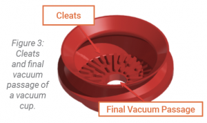 Although they may go unnoticed, internal features of vacuum cups can have a significant impact on the performance, as figure 3 illustrates. Internal cleats or ribs on vacuum cups provide a clear datum point where the product is held securely. Additionally, they provide increased frictional support for fast lateral movement or gripping in shear. Cup ribs can have specific designs such as channels to enable displacement of oil or liquid on the grip surface. This type of cup feature is popular in the steel-stamping industry, in which oil is present on product surfaces.
The flow through inner diameter (ID) of a vacuum cup can be insignificant, or it can make or break the system. Refer to the final vacuum passage in figure 3. Cups are mostly designed with fair ID sizes to support enough flow for its particular design. But if the application is high flow, to create a good, efficient seal on the product surface it is crucial to select a cup with an ID that can handle the maximum flow provided by the pump. Conversely, in a system with cups potentially not sealing on the product, it is advantageous to select a cup or cup fitting with a smaller ID to reduce unwanted leakage into the system. More leakage results in a lower final vacuum level.
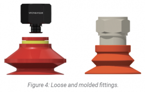 Figure 4 illustrates two common ways to mount a vacuum cup using a cup fitting. The loose-fitting approach is popular for smaller cups since the cup can be easily replaced by pulling it off the fitting and pressing a new cup onto the fitting. As obvious as it may seem, it is important to replace the cups correctly by pushing and twisting the cup onto the fitting, so they are installed well to maximize their life and performance. Cups with molded fittings are targeted to larger models and heavy-duty use. They are also useful for applications in which there is a significant resisting force against the cups, such as pulling stacked parts out of clamps or molds, or vacuum hold down for machining processes. The downside is that there is more work and cost involved to replace molded fitting cups since the cups need to be unscrewed to be replaced.
Depending on the manufacturer or cup model, the thread types can differ between NPT, NPSF, BSPT(R), or BSPP(G). Sometimes metric threads are used as well. BSPP(G) is often the preferred thread type for vacuum cups because it uses an O-ring seal that allows the cups to be installed at equal heights. Universal threads can also be used because they offer the same benefit. More information on pipe threads can be found in a tutorial you can access at https://vimeo.com/428544383.
This article discussed the basic features of vacuum cups and how to consider each based on the application. There are a multitude of cups that work for most applications. Scrutinizing every feature down to the last detail is unnecessary, but selecting and using an appropriate size and model has clear value. Qualified professionals can help find the right cup for an application.
This article is the opinion of the author, Dane Spivak of Davasol Inc., an industrial brand management firm with many clients. One of Davasol’s clients, Vacuforce LLC, based in Indianapolis, partners with the author on this article. Contact Dane Spivak at dspivak@davasol.com.
Share this information.
Related Posts


Sponsor

Sponsors