Automated Unloading with the Right Gripper Concept
By Mike Tuohey, Regional Marketing Manager, Americas, Piab USA
Injection molded parts can have simple, flat or very complex shapes. Accordingly, the end-of-arm-tool (EOAT) must be constructed in an automatic unloading process. The requirements increase if the parts to be removed are to be chromed later. Piab’s new division Robotic Gripping specializes in developing gripping concepts for the different levels of complexity. With this approach, the optimal balance between quality and cost requirements can be achieved for every component.
Plastic injection molded parts are used in a wide range of applications, ranging from simple flat geometries to highly complex curved geometries. The aim of manufacturing these components is to maximize the automation of the manufacturing process to minimize cycle times, reduce costs, and ensure consistent quality standards. The automatic unloading of finished components plays an essential role and places high demands on the design of the end-of-arm tools (EOATs).
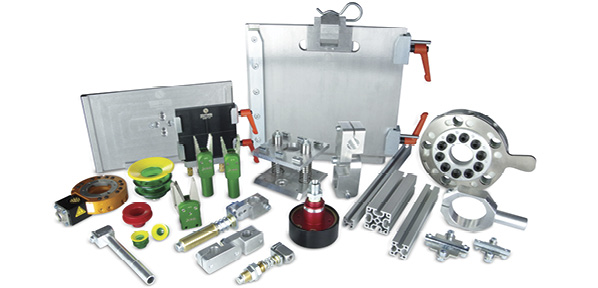
With the acquisition of both SAS Automation and Feba Automation, Piab combines the best of two worlds of gripper construction and can offer both grippers based on standard square profiles as well as on the basis of round profiles, depending on the component and the customer’s request.
Rectangular profiles are preferably used in simple or flat component geometries, which are removed on the core side. At this form of removal, the demolding of the component from the tool is carried out via ejector systems. For removal, the component can be picked up from the ejector pins or ejector units with simple components, such as suction cups or folding fingers and sprue grippers. A fully automatic removal with sprue separation is possible.
 The company’s gripper concept based on round profiles is ideal especially for complex, geometry-strong components, such as those used in the automotive industry, i.e., for bumpers, which are removed on the cavity half (on the nozzle side). It allows greater flexibility in terms of the positioning of the components on the gripper.
The lower weight of the gripper protects the mechanics of the robot and reduces its susceptibility to interference. Correspondingly, higher payloads or the use of a smaller robot are possible.
“The matrix side gripper carries out the de-molding from the cavity half of the tool. In the meantime, the gripper must actively deform the component via gripper lifting units and movable vacuum units in order to be able to mold it from the undercuts on the tool side. In this case, stress whitening or scratches on A-surface of the component (the visible side of the part) must be avoided at all costs, as they continue to be more visible after further process steps, such as painting or galvanizing, and thus usually do not pass quality control processes,” explains Rob Dalton, president of Piab Robotic Gripping Division in Xenia, Ohio.
As specialists in matrix-side grippers, Piab developed extensive knowhow to even remove parts with highly complex geometries from the mold without any damage.
A further specific requirement are extractions of components, which have to be galvanized—also known as chromed—later, because any mark and tiny scratches on the chrome surface would be immediately visible. Piab has developed a special gripper for the automated removal of such injection-molded parts. This gripper docks to the injection molding tool via special centering units. Flocked contour pieces, which correspond to the negative form of the component, take the component carefully and gently. The component is held in the negative mold on gripper fingers that touch the component only on the non-viewing side. In this way, even the most sensitive, already processed components can be handled easily and automatically in consistently high quality.
“Generally, we develop each gripper specifically on the basis of customer needs, the robot type used and the requirements imposed by the component. We work closely with our customers and construct each gripper based on the tool and component data provided to us in the CAD system. Depending on the size of the gripper, it is fully pre-assembled at our production site in Xenia, then completed and put into operation by our service technicians at the customer’s site,” describes Dalton of the implementation procedure for all gripper projects.
Share this information.
Related Posts


Sponsor

Sponsors