The Versatile Remedy: Pressure Compensated Flow Control Valves
By John Kelly, Engineering Manager, Kelly Pneumatics.
A pressure-compensated flow control valve is designed to provide a constant volume flow rate regardless of the pressure drop across it. By contrast, non-pressure-compensated flow control valves have a variable flow rate that changes when the pressure drop fluctuates. It is possible for pressure-compensated flow control valves to also compensate pressure fluctuations on either the supply (inlet) or the load (outlet) side of the valve.
One way to address the problem of changing flow based on a fluctuating pressure drop is to use a flow control valve with closed loop control. This involves adding a flow transducer or pressure transducer downstream from the valve that sends a signal back to a control system, representing the current downstream conditions. This feedback signal can be used to calculate real-time adjustments needed to maintain flow rate, which can be commanded to the flow control valve accordingly.
However, building closed loop flow control systems is complicated and costly. This typically involves a proportional integral derivative controller to accurately provide constant downstream flow rates. These are complex mechanisms that require experienced pneumatic and software engineers to build.
Mass flow controllers are another option. They use closed loop technology to provide stable flow rates with varying pressure drops. These flow control devices are a great option to avoid the high cost of developing a custom closed loop device. These controllers have an internal flow or pressure transducer, flow control valve, and proportional integral derivative circuit that can dynamically adjust the current flow output of the internal flow valve.
A primary issue with mass flow controllers is the need for a downstream transducer. Since the closed loop control requires a downstream transducer, it can be difficult to find mass flow controllers compatible with some media. For example, some corrosive or caustic gasses cannot be used with transducers.
Given the challenges of using a mass flow controller or building a custom closed loop flow controller, a pressure compensating valve may be a much better solution.
Operating principles
Flow control valves that are pressure compensated normally consist of a variable orifice and a pressure compensator incorporated into one valve body. Flow goes from the supply valve through the inlet and compensated orifice, around the compensated spool, through the variable orifice, and then out the outlet.
By adjusting the pass-through area of the orifice, the desired flow rate is set on the variable orifice. You can make this adjustment manually using a knob, screw, or lever on the valve or, alternatively, with electronic signals sent to an actuator attached to the variable orifice. The pressure compensator achieves a constant pressure drop across the variable orifice by modulating the flow of gas entering the valve. It also provides a constant flow rate across the valve by adjusting the orifice between the inlet flow and the compensator spool.
Variable orifices are made up of valve stems that have a pointed end that can move toward and away from a seat in order to achieve different sizes of openings. Whenever the tip of the stem is in full contact with the seat, the orifice becomes closed, and no gas can pass. With the stem tip moved away from the seat, the orifice opening becomes larger, and more gas passes through.
A spool valve with a spring anchors the pressure compensator. Compensation spools consist of a cylindrical barrel with a plunger that slides inside. Plungers have thin and wide sections along their length. As long as the lands and ports are adjacent to each other, they block gas flow. The wide sections of the barrel are called lands. Spools with narrow, wasted sections allow gas to pass through them.
By applying a force to the end of the spool attached to the valve housing, a spring keeps the spool attached to it. Flowing past the variable orifice in the outlet of the valve applies an additional force to the anchored end of the spool. There is a pressure gradient along the line leading from the pressure-compensated flow control valve to the load, such as a hydraulic motor or cylinder.
The gas that has passed the variable orifice but not yet reached the inlet and compensator is ported to the other end of the spool (the end opposite the end attached to the spring). A force is applied to the spool at this end by the gas that opposes the force applied by the load pressure and spring pressure. The opposing forces distort the opening of the orifice through which gas flows from the flow source, modulating the opening of the orifice until the forces at either end of the spool are balanced.
Consequently, gas flows from the supply, across the compensator spool, and through the variable orifice, while a constant pressure drop across the variable orifice keeps the flow rate constant regardless of changes in pressure between supply and load.
As gas temperature increases, viscosity also increases, affecting flow rate. Some pressure-compensated flow control valves incorporate a temperature-sensitive element that adapts the position of the compensator when gas temperatures and viscosity vary. This ensures a constant flow rate regardless of gas temperature and viscosity. By using a sharp-edged orifice design for the variable orifice, some designs minimize the variations in flow rate due to changes in viscosity.
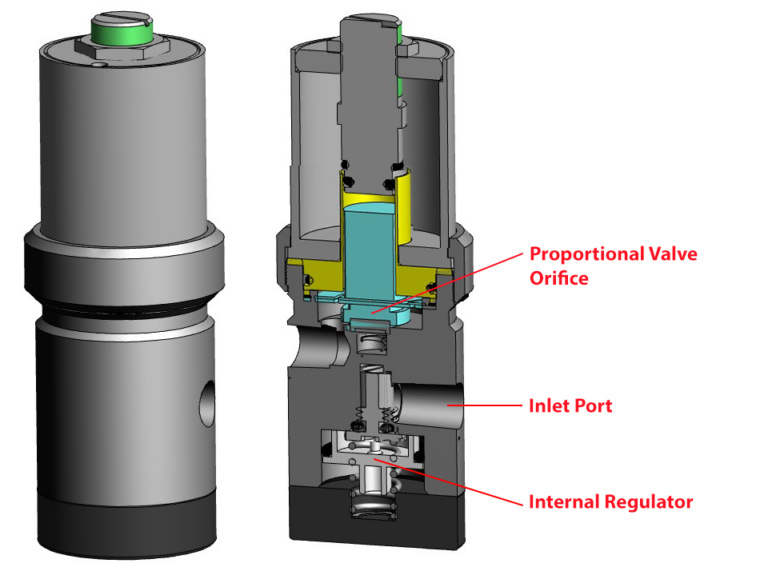
Kelly Pneumatics offers its pressure compensated proportional valve for projects that require a pressure-compensated flow control valve. There is a mechanical pressure regulator built into the unit, which lowers the incoming input process on the inlet port to the lowest operating working pressure recommended for the valve to output accurate flow rates. Lowering the pressure after regulation can achieve a consistent flow rate despite fluctuating input pressures. A proportional flow to the system is maintained so long as the incoming pressure does not drop below the minimum required pressure.
Applications
Pressure-compensated flow control valves are used in a variety of hydraulic applications. They are useful, for example, when it is necessary to maintain a constant speed on a hydraulic cylinder, regardless of the amount of load the cylinder is under. Because speed is directly proportional to hydraulic gas flow rate, a hydraulic cylinder’s speed depends on how much gas is flowing through it.
In a flow control valve without pressure compensation, the flow rate fluctuates depending on the load on the cylinder. A heavy load on the cylinder increases the pressure at the valve’s outlet compared to one with a lighter load. Changing the pressure drop across the valve alters the flow rate it delivers to the cylinder. Pressure-compensated flow control valves adapt to such pressure changes to maintain a constant flow rate that provides gas motion at constant speed
Pressure-compensated flow control valves are also useful in maintaining constant rpm of a hydraulic motor independent of load on the motor. Much like the example above, changing loads on the motor results in a fluctuating pressure drop across the valve ahead of the motor. Pressure-compensated flow control valves compensate for these fluctuations by maintaining the hydraulic motor’s rpm at a constant level.
An integral part of a pressure-compensated flow control valve is the pressure compensator. A valve without it would have a variable flow rate when pressure across the valve varies. Forcing more gas through the valve as a result of a higher pressure drop raises the flow rate; a lower pressure drop lowers the flow rate.
By automatically adjusting the volume flow rate from the flow supply to the variable orifice, the pressure compensator keeps the internal pressure drop across the variable orifice constant, regardless of the change in pressure drop between the inlet and outlet. With a constant internal pressure drop across the variable orifice, the valve produces a constant volumetric flow rate regardless of the pressure differences between the valve inlet and outlet. This decreases the incoming input process on the inlet port to the lowest operation working pressure for the valve to output accurate flow rates. After regulation, this lowered pressure is applied to the proportional valve orifice, thereby allowing for consistent flow rates even with fluctuating input pressures. So long as the incoming pressure does not drop below the minimum required pressure, accurate proportional flow is maintained to the system.
Share this information.
Related Posts


Sponsor

Sponsors