Transforming Our Thinking: What in the World is a VDT?
![]()
Ok, let me see a show of hands. How many of you are familiar with a turbocharger? Now keep the hands up so we can count. I see the NASCAR group is responding enthusiastically. Others seem to be a little hesitant. That’s ok. I will explain.
A turbocharger is a device that is typically placed in the exhaust stream of a combustion engine. It consists of two impellers that are connected by a common shaft. The exhaust gas of the engine drives one impeller, which acts as an air motor. The connecting shaft turns the other impeller, which becomes an air pump/compressor. The inlet to the motor side of the turbocharger is from the engine exhaust. The inlet to the pump/compressor is open to atmosphere. The outlet of the motor side is directed to atmosphere while the outlet of the pump/compressor is directed to the engine air intake. (See the Turbocharger Symbol) The dense, oxygen rich air improves combustion and increases the efficiency of the engine.
This is a simplified explanation, but it serves a purpose. The point is that the otherwise wasted energy in the exhaust gas is now regenerated by driving the pump/compressor. The turbocharger functions as a displacement transformer. Relatively low pressure, oxygen depleted exhaust air is used to compress and drive oxygen rich air into the combustion chamber.
![]()
The turbocharger is a displacement device, but it is not a fixed or positive displacement device, whereas a pneumatic Fixed Displacement Transformer (FDT) is both fixed and positive. That means that the FDT has a specific flow rate (cm3 or in3) for each revolution. It also can receive or exhaust from any port, depending on the application. When placed in a circuit, it can be used for flow augmentation, flow dividing, flow combining, or pressure intensification.
![]()
In figure 1, the circuit shows an example where a pneumatic FDT provides all four of those functions, responding to the pressure demands of the system. In the example, an FDT is used to control a compacting cylinder. Two pilot-controlled directional valves determine the flow paths in and out of the transformer. As the cylinder begins to extend, the resistive pressure is low so neither directional valve is shifted. The transformer functions as a flow augmenter, drawing air from the atmosphere. This air joins that which is coming from the receiver. The power entering the FDT must equal the power leaving the FDT and so the increase in flow produces a reduced pressure to the cylinder. As the pressure at the cylinder rises, the bottom directional valve is piloted to cancel the flow from the atmosphere and direct only the flow from the receiver to the cylinder.
When the load pressure reaches the setting of the upper directional valve, it shifts and diverts a portion of the flow to atmosphere. This reduces the flow to the cylinder and intensifies the pressure. The FDT provides three discrete pressure and flow combinations with a constant flow from the source. The effect is that of a three-speed transmission. When the 4-way directional valve is shifted to retract the cylinder, the cylinder will retract at high speed if there is a low-pressure requirement.
The circuit also works in an application with a pneumatic motor where there is a need for a high starting torque, then a diminishing running torque (see figure 2).
![]()
However, despite its flexibility, the FDT is limited precisely because it has a fixed displacement. It can only provide a finite number of combinations.
The Variable Displacement Transformer (VDT) is a modification of the FDT. One or more of the chambers has a variable displacement. It is this feature that makes it suitable for true power control. When combined with a variable flow source from a receiver, it provides a way to draw only the energy units needed for the actuator to do the work. It removes the need for restrictive flow and pressure controls while using the power demand to control the number of energy units drawn from the source.
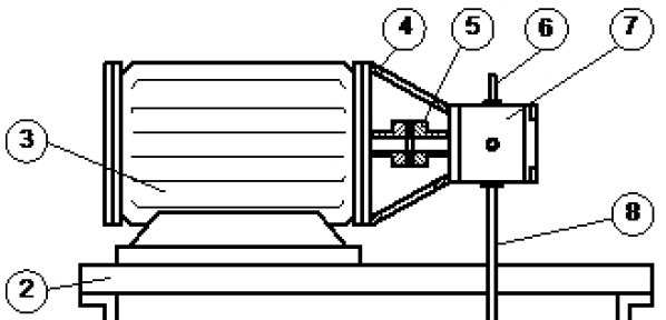
The VDT can be made up of a single fixed displacement motor connected to a variable displacement motor, or two variable displacement motors that are mechanically connected. Under development are several versions where there is a single rotating group with two displacement chambers, making for a more compact and versatile product (see figure 3).
![]()
![]() When the FDT is replaced with the VDT in the compacting circuit, we see that the VDT makes a stepless transmission. As the load on the cylinder increases, the amount of air drawn from the atmosphere is diminished until it reaches zero. The pilot controlled directional valve shifts and the VDT becomes a pressure intensifier. The VDT sends a constant power to the cylinder by matching the flow to the pressure (see figure 4).
When the FDT is replaced with the VDT in the compacting circuit, we see that the VDT makes a stepless transmission. As the load on the cylinder increases, the amount of air drawn from the atmosphere is diminished until it reaches zero. The pilot controlled directional valve shifts and the VDT becomes a pressure intensifier. The VDT sends a constant power to the cylinder by matching the flow to the pressure (see figure 4).
Thinking differently about the way we transfer energy through fluids is critical for the future of the industry. Energy loss associated with velocity control has become the accepted cost of doing business. This does not need to be the case. The VDT is not just a novel idea that has no practical application. It has the potential to save billions of dollars in energy costs across the globe. Wherever there is an orifice used for velocity control, there is the potential for a VDT to eliminate the energy loss.
If you have any questions, please contact Dan Helgerson at Dan@DanHelgerson.com. Visit Watts It All About to read Dan’s previous articles.
Share this information.
Related Posts
From Outer Space to Under the Sea, Hydraulics Put the Fun in the Entertainment Industry
Don’t Follow The Crowd, Mount Your Hydraulic Pumps…For Life

IFPS Upgrades Hydraulic Specialist Certification
Vacuum Hose and Fittings
Integration of Ferrous Density and Particle Count for Automated Ferrography Analysis of Abnormal Wear Conditions

New Sealing Technology and Materials for More Efficient and Sustainable Heavy-Duty Equipment
Sponsor

Sponsors