Understanding the Function of Valves

Fig. 1.45 Unloading Valve Symbol
Unloading valves (Fig. 1.45): When fixed displacement pumps are used in accumulator or high-low circuits, unloading valves are used to minimize the power requirements.
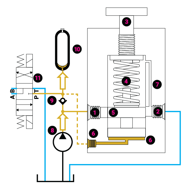
Fig. 1.46a Unloading Valve Closed, Low Pilot Signal
They do this by allowing a pump to unload to the reservoir at low pressure when its flow is not needed. The valve is externally piloted6 and has an isolation check valve, 9, in the circuit. As shown in Fig. 1.46, the fixed displacement pump8 is charging an accumulator, 10, with the directional valve, 11, in the center position. The P port is closed. As the accumulator is filled, the pressure builds to the setting of the unloading valve. The pilot signal lifts the spool and directs the pump flow to the reservoir. The sudden loss of pressure at the pump outlet causes the isolation check valve, 9, to close and lock in the pressure at the accumulator. Because the pilot line is connected downstream from the check valve, the signal remains and allows all pump flow to be diverted to the reservoir at low pressure. This condition remains until the accumulator pressure drops below the setting of the spring, 4.
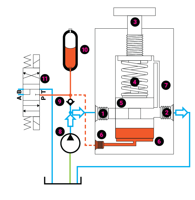
Fig. 1.46b Unloading Valve Open with Signal Beyond Isolation Check Valve
With the loss of pilot pressure, the valve closes, and pump flow is redirected to the accumulator.
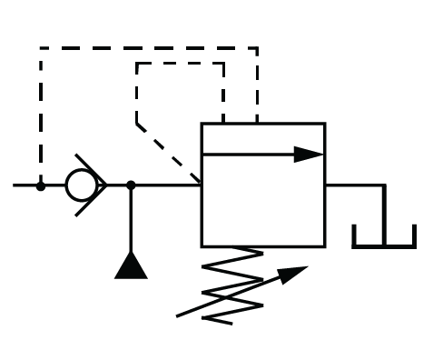
Fig. 1.47 Unloading Relief Valve Symbol
Unloading relief valves: It is sometimes necessary for an unloading valve to also have a relieving function. This is done by adding a separate relieving circuit within the valve body (Fig. 1.47 for graphical symbol).
 Flow control: Flow is the movement of fluid. Flow is always from a region of higher pressure toward a region of lower pressure; upstream to downstream. Flow rate describes an amount (volume) of fluid that is moving over time. It is commonly expressed as liters per minute (lpm) or gallons per minute (gpm). It is the flow rate that determines the speed of a cylinder or motor. Consequently, flow control is sometimes referred to as speed control.
Flow control is power control. It is possible to have pressure without flow, but there cannot be flow without pressure. The combination of pressure and flow is power.
The flow rate through a restriction is determined by the following:
- The pressure upstream of the orifice.
- The pressure downstream of the orifice.
- The size of the orifice.
Fluid temperature also plays a part in the flow rate because warmer fluid is less viscous and may slip more easily through a restriction. This may reduce the pressure loss through an orifice, increasing the flow rate.
The restriction can be in the form of a simple orifice disk that is placed in the plumbing. An equation is used to determine the pressure consumed across the orifice at a given flow. The orifice is not adjustable and is used where there is a relatively constant pressure available. If there is a change in upstream or down- stream pressure, the flow through the orifice will change accordingly.
Needle Valve (with Symbol)
A needle valve is an orifice that is adjustable. It adds a restriction to the flow path of fluid, extracting energy as heat. The flow through the valve will be determined by the upstream pressure and the pressure required to move the load. Even with a constant upstream pressure, a change in the pressure required to move the load will make a change in the ∆p and a consequent change in the flow rate. Neither the orifice disk nor the needle valve can be used to establish a fixed flow if there is any variation in the ∆p.
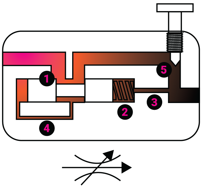
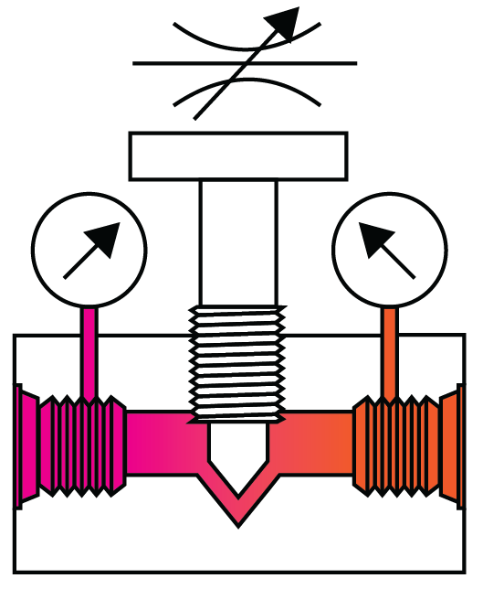
Pressure-Compensated Flow Control (with Symbol)
Pressure compensation: A pressure-compensated flow control is a device with two restrictive orifices in series. The first restriction 1 is at the compensator spool. The second restriction is at a control orifice, which could be a fixed disk or an adjustable needle valve 5 as in the picture.
One side of the compensator spool is piloted from upstream of the control orifice 4. The other end has a bias spring 2 and is also piloted from the valve outlet 3. The bias spring pressure is typically about 0.6 MPa (90 psi). The compensator spool modulates so that the pressure loss (∆p) across the restriction at 1 maintains the pressure at 5 so that it is always the bias spring pressure above the load pressure. The arrangement causes the constant ∆p across the control orifice, which produces a constant flow, regardless of changes to supply or load pressure.
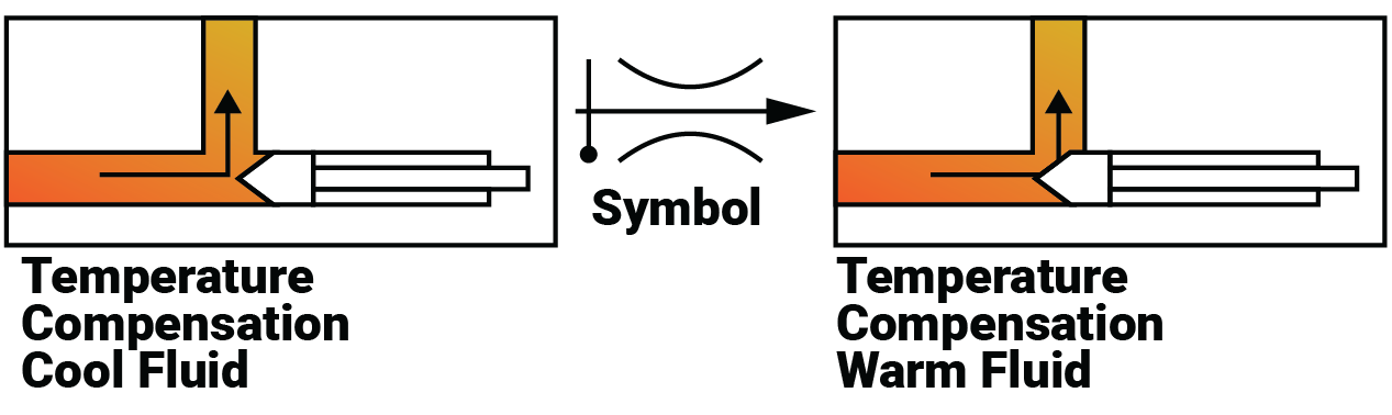
Temperature compensation: The viscosity of hydraulic fluid is affected by temperature. A change in viscosity also alters the ∆p across an orifice, which in turn affects the flow. Temperature compensation is achieved by using a material that expands and contracts with temperature changes to modulate the flow to maintain set flow rate.
Anti-lunge control: A pressure-compensated flow control valve is a normally open valve. At start up, full flow may be directed to the actuator until the compensator can react to the pressure. This will cause the actuator to lunge momentarily at an uncontrolled speed. Some flow control valves include a feature that offsets the compensator spool to a controlled position until the input and output pressures can position the spool. This feature is called anti-lunge control.
Flow dividers: A flow control limits flow, while a flow divider does not limit flow but rather distributes it. Two identical cylinders or motors that must operate at the same speed but under different loads will each have a different power requirement. If the actuators must be synchronized but driven from a single source, the input power must be distributed to meet the demands of each.
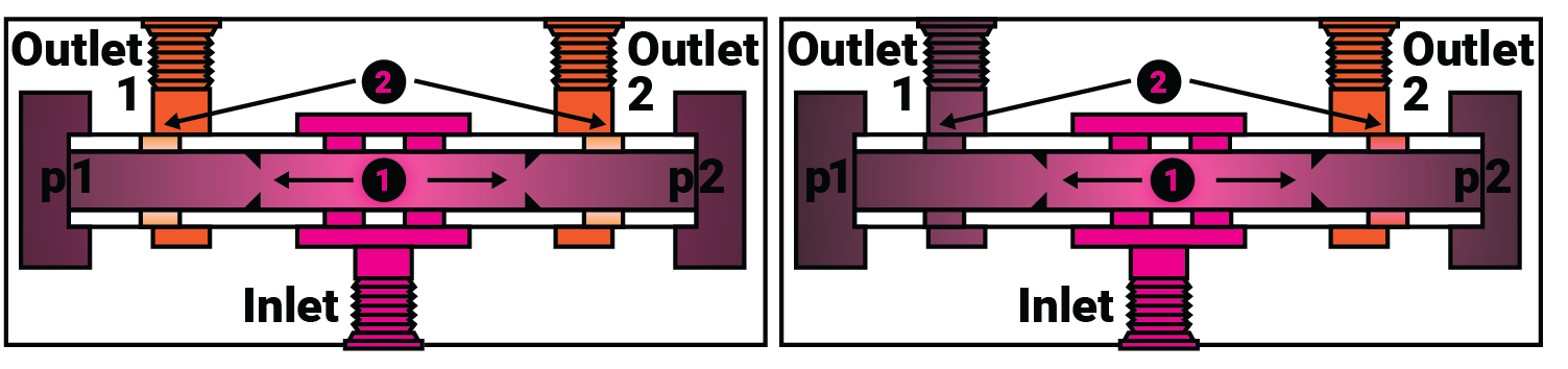
Fig. 1.48 Flow Divider Showing Even Flow
Flow Dividers/Combiners
Spool-type: Spool flow dividers are restrictive devices that regulate the power by using a set of two fixed orifices 1 in series with a set of two variable orifices 2. The variable orifices modulate, adding restrictions that equalize the pressure at p1 and p2. If the outlet pressures are equal, the spool is centered with the variable restrictions providing equal resistance. If the pressures at the outlets are different, the system becomes unbalanced, and the higher pressure moves the spool toward the lower pressure port. This decreases the restriction at the higher pressure port and simultaneously increases the restriction to the lower-pressure port, equalizing p1 and p2. This provides a constant pressure drop and constant flow across the two fixed orifices. The inlet pressure must be high enough to meet the greatest demand. The power is regulated by dissipating the excess energy as heat. The image in Fig. 1.48 shows a flow divider that splits the flow evenly. By changing the size of the fixed orifices 1, the flow can be split to ratios other than 50/50.
Flow can be reversed through this spool divider, but it will not be combined proportionally. Additional features can be added to the spool that will make it into a flow divider/combiner. A valve with these features will have a model number that will indicate that it will both divide flow and combine flow proportionally.
Test Your Skills
1. In order to have flow, there must be:
A. No resistance to the movement of fluid.
B. A directional control valve.
C. A flow control valve.
D. A pressure differential.
E. Equal pressure.
2. Restrictive-type flow controls:
A. Save energy.
B. Limit the power to an actuator.
C. Are always variable.
D. Cannot be pressure-compensated.
E. Cannot use sharp-edge orifices.
See Solutions
Share this information.
Related Posts

Sponsor

Sponsors