Optimizing Pulse Dust Filters
High flow-short duration pulses caused by compressed air-powered dust filter cleaning can cause excessive pressure differentials in a compressed air system and affect pressure-sensitive equipment in close proximity to these devices. These filters are located in many agricultural facilities to protect against environmental pollution caused by powder and dust being released from the top of storage silos and process exhaust. Students of Compressed Air Challenge (CAC)’s Fundamentals of Compressed Air Systems seminar learn of an innovative way to prevent these pulses from causing trouble in a system.
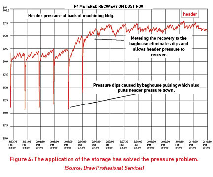
 Fig. 1 shows a typical filter housing arrangement where a bank of blast valves fed by a manifold, which is usually an oversized piece of pipe, is situated on the outside of the filter bank enclosure. To keep the filter elements clean, a control system opens each valve one by one in a timed sequence, causing a blast of compressed air to be released. The force of this blast shocks the filter elements and knocks out the entrained dust, renewing the element for further operation. Each blast lasts between one-tenth and one-quarter of a second, and when it occurs, a very high flow passes through the blast valves. In the case of Fig. 1, the supply lines, filter, and regulator must pass about 1,000 cfm of air for one-tenth of a second for each pulse. In this particular case, the supply line was one inch in size, and when the pulse passed through it, a very high-pressure differential developed, which starved the blast of the compressed air required for proper cleaning force. The rush of air feeding the blast also robbed nearby piping of compressed air, causing a large fluctuation in air pressure. Fig. 2 shows the pressure falling from above 90 psi to as low as 60 psi during each pulse.
Due to the low pressure, the filter elements were not being cleaned properly. A solution to this might have been to increase the pulse duration and frequency, and crank up the pressure, but this would have consumed extra quantities of expensive compressed air, increasing the cost of operation significantly and likely not adequately solving the issue.
To solve the problem, some small local storage receiver capacity (60 gallons) was installed plus a check valve and a needle valve. The check valve prevents the compressed air stored in the local receiver from flowing back into the plant to feed some other air demand. The needle valve slows the flow of air so that large pulses do not flow though the small supply line, filter, and regulator. The needle valve is set so that the compressed air slowly fills the local receiver, which reaches its final pressure just as the next blast of compressed air is called for by the blast controller. This acts to average the flow in the supply lines to a more manageable 36 cfm, which reduces the high-pressure differentials.
This is just one example of several “tricks of the trade” discussed in the CAC Fundamentals training. Many more improvement measures are mentioned in the course material and in the accompanying Best Practices for Compressed Air Systems Manual that each course participant receives. CAC training has been scheduled in numerous areas of the country and may be happening at a location near you.
By Ron Marshall, Compressed Air Challenge
For more information and a schedule of training opportunities, visit www.compressedairchallenge.org.


