Universal Vacuum Grippers and End of Arm Tools
By Dane Spivak, and illustrations by Daniel Pascoe, Davasol Inc.
Design criteria for nearly all systems follow many of the same rules, and it is no different in automation and manufacturing. There are recurring buzzwords thrown around when discussing how to approach a potential solution. Modular, flexible, one-size-fits-all – often broad and vague conditions, so what does all this mean?
This article contains strategies for vacuum lifting and gripping tools to meet the above conditions. Many applications require the need to pick and place or hold down parts of various shapes, sizes, and weights. Using a single tool with a reasonable design to accomplish this task is certainly ideal. We will refer to such a solution as a universal vacuum tool.
Abstract
The first thing that comes to mind when designing a universal vacuum tool is how to handle various product sizes when vacuum cups do not seal on the target load. The primary focus of this article will discuss different techniques to implement in overcoming this challenge, and the pros and cons of each. Other design strategies will be touched on as well.
Venturi Cup Isolation
 Venturi vacuum generators use compressed air to produce vacuum. They are significantly smaller than vacuum pumps allowing for installation closer to the cups or directly onto the tool itself. Venturis have no moving parts, and therefore can be turned on and off continuously at fast rates using pneumatic valves. In a universal vacuum system, this can prove to be very advantageous as a single or group of cups can be completely independently controlled by its dedicated venturi.
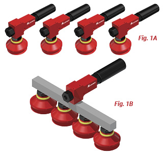
Figure 1A shows four venturis connected to their own vacuum cup. This means each cup can be turned on/off individually and their performances are unaffected by one another. So when lifting a product, regardless of contact with one or four cups, the venturis will provide maximum vacuum levels and lifting forces. Unlike a single venturi attached to all four cups in Figure 1B. This would cause all four cups to be dependent on the same vacuum source. Therefore, if one or more cups do not seal on the product, the other cups that are in contact will have a reduced vacuum level due to atmospheric air entering the vacuum system through cups that are not sealed.
Using the dedicated venturi approach described previously on a universal tool can be simple and practical when a low number of cups are in use. As the need for more cups increases, this design tends to be less efficient due to high compressed air consumption, and an increase in the total number of parts, maintenance, and overall cost.
Pumps and Control Valves
 When using a typical electric vacuum source, such as a rotary vane pump or regenerative blower, the pump is designed to run continuously. Unlike the venturi isolation in the previous section, it is not economical to use multiple electric pumps and turn them on and off frequently. Doing this can quickly result in a loss of performance, maintenance needs, or failure altogether. For this reason, isolating groups of cups should be approached differently with an electrical pump.
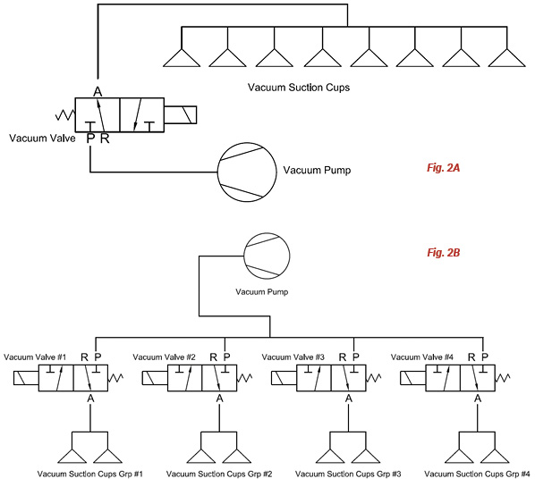
Turning vacuum on/off is accomplished by utilizing vacuum control valves between the pump and cups. Figure 2A shows a common vacuum circuit where a single valve is being used to control vacuum to an array of cups. In this case, all cups are opened at the same time and reliant on the same vacuum source.
Figure 2B shows four vacuum valves controlling different cup sections. This offers a choice of which vacuum cup group should be used. So if Group #1 and Group #2 seal against the product, these valves can be selected to turn on while Group #3 and Group #4 remain closed. This way sections #3 and #4 do not open and prevent free air flow into the vacuum system, which would cause lowered vacuum levels and possible failure.
Powering the valves to grip at different times is not ideal. If section #1 grips a part, then some time later valve #2 turns on to grip another part, opening valve #2 creates brief exposure to atmospheric air between valve 2 and its cups. The result is a drop in system vacuum level, which affects the gripping and lifting force in section #1 as they both rely on the same pump. However, the reverse action is feasible. If valves #1 and #2 turn on to pick up two different parts, they can exhaust the vacuum to drop the parts separately. Exhausting the valve allows atmospheric air through the valve and into the cups, but closes atmospheric air to the pump circuit. Therefore, exhausting or releasing vacuum grip can be done safely with independent valves.
Using valves to section a grid of vacuum cups can be effective and plausible for universal tool designs. This approach is ideal when handling only a few different sizes of products that are positioned accurately. The product sizes, dimensions, and locations should be well understood for consistency.
Orifice Screws & Minimizing Leakage
Using less sources to generate vacuum is usually the preferred method regardless of venturi or pump choice. One vacuum source compared to multiple vacuum sources is generally easier to deal with in terms of costs, maintenance, and energy consumption, as well as have a much more simplified design. Limiting the amount of leakage or atmospheric air entering a vacuum system is one strategy to use a single vacuum source to take advantage of the benefits.
Reverting to the abstract, handling various product sizes with a single tool produces situations where vacuum cups do not seal against the product surface. Previously, I explained how to completely shut off leakage caused by this process or have completely independent cup sections. However, let’s analyze how to reduce the leakage from unsealed cups while still having the ability to safely grip and control products under vacuum.
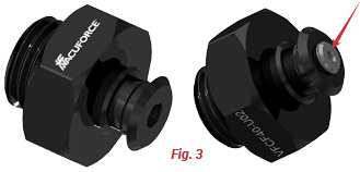 Figure 3 shows a cup fitting with and without an orifice screw inserted. The purpose of the orifice screw is to restrict air flow (leakage) into the common vacuum system. The smallest area or diameter where air passes through is in direct relation to the volume of air flow entering the vacuum system. Therefore, it is ideal to downsize the restrictive diameter as small as possible to limit unwanted leakage. However, the restrictive orifice should not be infinitely small since flow is required to create a seal for the vacuum cups. Additionally, the orifice should be large enough to allow debris, water, and dust to pass through and collect inside the filter instead of clogging the vacuum line. With that said, the common restrictive orifice diameters as demonstrated by the orifice screw in Figure 3 are around ø1mm to ø2mm.
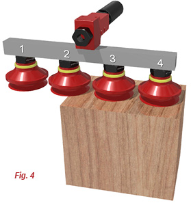 Figure 4 illustrates a typical application for using vacuum cups with orifice screws. Cups 1 and 2 are not sealed against the product. The installation of an orifice screw in the cup fittings minimizes leakage and allows a secure grip of the product using cups 3 and 4 as shown. It is important to understand the worst case scenario to allow proper sizing of the vacuum pump or venturi. The tool design and pump sizing heavily rely on the situation where the most cups are exposed to leakage and relatively lower vacuum levels are present.
A quick note about common pump/generator selection for restrictive orifices and minimizing leakage. Regenerative blowers are often a better choice. Although their maximum possible vacuum levels are typically lower than other types of vacuum pumps, they provide higher vacuum flow rates which can achieve higher vacuum levels when leakage is involved compared to other forms of vacuum generation. Venturis can be used, but may not be as effective as leakage increases. Rotary vane pumps are usually not recommended since they are designed to run at high vacuum levels consistently. They do not handle leakage well or run efficiently under 20”Hg.
Velocity Fuses – The Self-Closing Valve
A velocity fuse is a term more commonly used in hydraulics as a safety device. It is a device which monitors the flow rate of the fluid, and if its maximum flow is exceeded, it will close until the pressure is relieved. In vacuum lifting, the velocity fuse definition is no different though it is certainly used in a different manner. The following section will go over how we can apply this technology to a universal vacuum tool. In vacuum lifting, the velocity fuse is often described as a check valve, sensing valve, or self-closing valve, which is the terminology we will use going forward for relevancy to the topic.
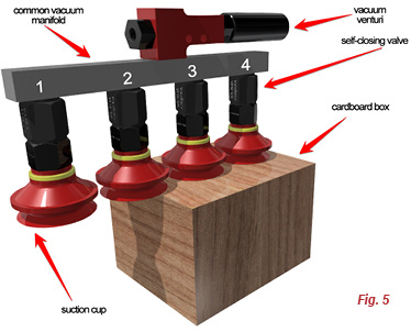 Figure 5 shows self-closing valves connected to four vacuum cups. The vacuum cups, #1 and #2, are not sealed against the box being handled. When vacuum is applied, the self-closing valves on cups #1 and #2 experience an in rush of atmospheric air which closes the valves, isolating the attached cups from the common system. Cups #3 and #4 are sealed against the box. When the vacuum is turned on, the volume of sealed air between the self-closing valve and the cup face is not large enough to close the valve. Therefore, the self-closing valves remain open allowing vacuum grip against the box surface. When vacuum is turned off, the cups #3 and #4 release the box. The self-closing valves attached to cups #1 and #2 return to their open rest position, ready for the next cycle start.
There are different designs to self-closing valves. Certain designs allow for the bottom seat of the self-closing valve to be adjustable. This feature controls how much flow it takes to close the valve, or in other words, tweak its sensitivity based on the spring tension allowing it to be versatile. Other models will have no spring at all, and essentially have a free-floating ball. This type tends to be more sensitive and does not work well if the tool is angled since it relies on gravity, or if high velocity movement is involved in the production cycle. There are also models that use a flexible rubber flap instead of a ball. The velocity fuse concept still applies.
Let’s move on to applying the same self-closing valve in Figure 5 to create a universal vacuum tool. Figure 6 shows a vacuum circuit with a self-closing valve connected to each cup. The tool is connected to a control valve and vacuum pump to complete the system. This design allows parts of any size within the cups weight capacity to be lifted. Regardless of the number or location of cups sealed against the product, all cups in contact can achieve the maximum allowable vacuum level since the cups that do not seal completely shut off thanks to the self-closing valves. This is very powerful since no sensors are required to choose which valve to close. It’s all done automatically due to air flow. Additionally, full vacuum levels and lifting forces are attained as leakage is virtually eliminated.
Pump/generator type is not critical when using self-closing valves. Sizing for adequate flow to close the self-closing valves is the important aspect. All self-closing valves require different amounts of flow to close, and as previously mentioned, some are adjustable. A general rule of thumb is to use a minimum of 1CFM for a 2” (50mm) cup.
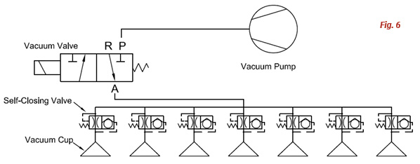
Vacuum control valves assist in generating more flow. Looking back at Figure 6, the control valve creates a vacuum reservoir between itself and the pump. When the control valve turns on, a large inrush of air is generated. This encourages the self-closing valves to close confidently. The vacuum control valve offers this benefit unlike a direct connection to a venturi generator, which does not need a vacuum valve. The venturi would ramp up vacuum when the pneumatic valve is turned on instead of having it stored.
Conclusion
Universal vacuum tooling design has many possible avenues. This article covered techniques including venturi cup isolation, control valve sections, minimizing leakage, and self-closing valves. Each application is unique and has its own requirements. Professional help should be sought out to meet all needs and provide a safe solution using best vacuum practice.
Share this information.
Related Posts


Sponsor

Sponsors