Vacuum Filters
I have previously written about the importance of filtration in vacuum pick-and-place applications and in other tasks where dirt and dust might be present. This article explains the three most common types of vacuum pick-and-place filters that, depending on the application, should always be used to ensure upstream equipment does not get contaminated and consequently fail.
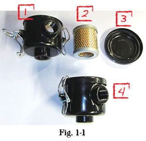
I have seen many applications that do not use any filtration, and in the majority of cases, it seems this is because the user, or indeed the machine builder, was not aware of alternatives to the typical larger models (as shown in Fig 1-1).
A lot of production machinery use smaller point-of-use vacuum generators that operate using compressed air. These small generators (also referred to as a “venturi” or “ejector”) have very small orifices for air conveyance, some as small as 0.5 mm in diameter. As you can imagine, if dirt or dust was drawn into these devices, it wouldn’t be long until these orifices got plugged and subsequently stopped working—and certainly without any prior warning to the user. The main problem with this is that the generators are rarely repairable and therefore, considering their low cost (sometimes in the $20-$30 range), are simply replaced. This is not good vacuum practice, and this article offers a possible alternative method of installation to this very common problem.
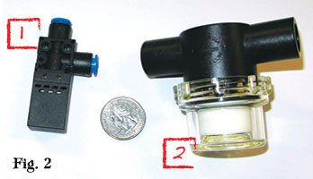
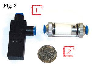
For scaling purposes, a U.S. quarter coin has been placed in Figs. 1, 2, and 3. These images show a very typical smaller-size venturi (1) that generates about 1 cfm of vacuum flow—ideal for single-cup applications as shown in Fig. 3-2. Fig. 1 utilizes a commonly found vacuum filter (2) that is about as small as this style is available at 1/4 NPT port. Quite clearly, this filter is overkill due to its physical size for the task and is difficult to connect together with the generator. This is the main reason why application engineers, unaware of smaller and different styles of filter types, avoid filters altogether.
Fig. 2 shows a much smaller filter (2), but, for the same reason, these are rarely employed in point-of-use generator applications because of their considerable larger dimensions compared to the generator.
Fig. 3, however, employs an ideal “inline” filter unit that has comparable dimensions and also utilizes the same ؼ” push-to-connect fitting as the generator. This filter can be simply installed right next to either the cup or the venturi by simply cutting the corresponding ؼ” tubing and joining each end to the filter assembly.
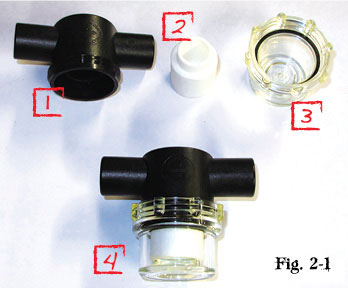
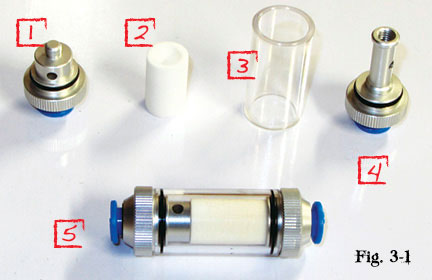
Of course there is a cost involved in procuring these filters. The filters are about the same price as the smallest generators and, in some cases, considerably less, particularly if the generator is a more technical “multi-stage” unit, which can easily cost upwards of $100. Even a “throwaway” filter ought to be changed when it is saturated (a known value) instead of waiting until it suddenly fails. This is in line with good maintenance practice. The filters (shown in Fig. 3-1) require a simple element change (2) rather than a complete filter unit replacement once dust or dirt has saturated the very low-cost element. The transparent filer body (3) allows easy inspection, unlike the inside of a generator. Changing the element requires the simple unscrewing of the end caps (1&4), which can be administered by the machine operator before machine start up or during a scheduled maintenance program by maintenance personnel.
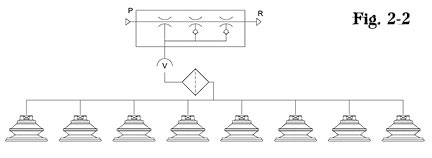
For larger installations (as illustrated in Fig. 2-2) where the generator is being used on numerous vacuum cups, a larger filter (such as the one shown in Fig. 2-1) can be used. These are commonly available up to 1-1/2 NPT with flow capacities in excess of 180 scfm. Again, these filters have a very simple element (2) change requiring only the removal of the filter bowl (3). The body (1) of this filter can remain in place on flexible or rigid piping during this procedure.
Filters like those shown in Fig. 1-1 are normally reserved for vacuum pump applications where continuous operation of the vacuum source is present and vacuum valves are used to turn vacuum on and off to the application. These filters are sometimes regarded as “heavy-duty” units and come with various element types, such as pleated paper or polyester for damp applications to prevent the paper element from getting saturated with water. These filters are available in various porosities, but 7µ (0.007 mm) filters normally are used with vacuum pumps. Large port sizes up to 4″ NPT are available, and for very large vacuum flow applications, flanged models are often utilized, particularly in centralized vacuum systems.
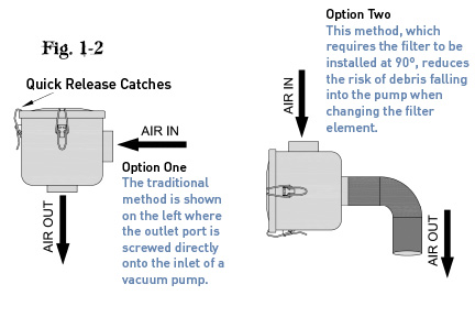
However, care should be taken during installation. The obvious way for these filters to be installed is with the lid (3) in the horizontal position. The problem with this orientation is that when the filter element is removed, dust that has gathered on the outside of the element falls inward and straight into the pump inlet—obviously not a situation any maintenance engineer wants to experience. Therefore, and as illustrated in Fig. 1-2, the filter should be installed at 90º to prevent this maintenance dilemma from occurring.
Using vacuum filters on any vacuum system is recommended. Different vacuum component manufacturers offer different types of vacuum filters, and some in fact do not offer any of them! Always ensure that the user experiences the best method rather than simply what is found to be available quickly from your normal “go-to” supplier.
This article is intended as a general guide and as with any industrial application involving machinery choice, independent professional advice should be sought to ensure correct selection and installation.


