Vacuum Measurement
By Dan Pascoe
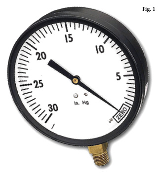
Often missing from a vacuum system is something to measure the vacuum level such as a vacuum switch or a vacuum gauge such as shown in Fig. 1.
A vacuum gauge is a low-cost option for troubleshooting and production efficiency. Vacuum pumps are selected based on two fundamental criteria: flow rate and vacuum level. The flow rate is determined by understanding the vacuum level required. Any vacuum pump or generator (air-powered venturi) will give you the performance shown in the manufacturer’s catalogue. However, the flow rate of a pump or generator will determine if the system can maintain the desired vacuum level in the actual application.
For example, if there is a leak in the vacuum circuit, the vacuum level might fall because the pump or generator cannot “keep up” with the loss. Imagine sucking through a straw with your hand on the other end. You can create a vacuum easily, crushing the plastic straw with ease. If the straw splits, maintaining a vacuum is a lot harder. That’s why a larger vacuum flow will be required to offer extra capacity to compensate for this leak.
If a process requires a certain vacuum level to fulfill its production design needs, a vacuum gauge should be installed to offer the user a visual indication of system performance.
Obvious enough. However, in vacuum lifting with vacuum cups, more often than not a vacuum gauge is not installed. There is rarely a good reason for this. The standard vacuum gauge as shown in Fig. 1 is a very low-cost solution to vacuum measurement. A simple bourdon tube design, normally manufactured in brass for all wetted parts (wetted parts refer to the parts of the gauge in contact with the media—oil, air, etc) with center back or stem-mounted threads that connect directly or indirectly to the vacuum line. These gauges offer an analogue reading of the vacuum level at that point in the system.
Placement of these gauge(s) in a vacuum system is important. Many vacuum generators offer a vacuum gauge integral to or connected to the main vacuum port. In centralized vacuum systems where one venturi is being used for several vacuum cups, the gauge reading at the venturi could be significantly different from the reading taken at the vacuum cups due to length of tubing or poor choice of fittings and other pipe connecting components. Quite often in a centralized system, the venturi is far from the working end of a vacuum-handling system, the vacuum cups. Having a gauge or indeed multiple gauges in the vacuum circuit offers considerable insight into what’s happening in the system and also significant problem-finding advantages.
One of the questions often asked is, “Why won’t my cups pick up the product?” I always ask what vacuum level they are achieving and 90% of the time the answer is, “I don’t know.” Without that information, a prognosis is certainly a more complicated exercise, particularly if this is a “phone-in” question. Vacuum level can quickly determine the obvious fault in a problematic vacuum system.
So a vacuum gage is a very important indirect component in a successful vacuum system. However, there are many different types of a vacuum “gauge.” The vacuum gauge as shown in Fig. 1 is very familiar, offering a vacuum reading of 0-30“Hg. These gauges are available in various diameters, the most common being from 1“ (25mm) through to 4″ (100mm). The port connection is either in the center of the rear face or stem-mounted, depending on user preference and positioning in the vacuum line. Glycerin-filled gauges are popular particularly on processes with a high cycle frequently as the glycerin liquid dampens the mechanical movement of the bourdon tube assembly. Dry fill gauges will oscillate very quickly in a high-cycle application, making it difficult to read by the user.
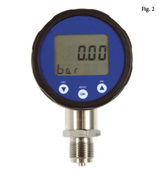
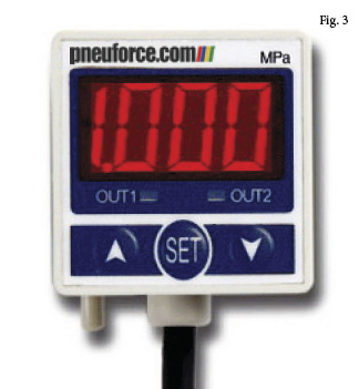
Digital gauges as shown in Fig. 2 are not commonly used as they are more expensive than the mass-produced bourdon tube type. They are able to withstand more abuse as they have a solid state “mechanism” that is able to withstand considerable oscillating pressure spikes and over-pressure scenarios. They are also easier to read for an exact value, but an analogue gauge (dial gauge) offers a quicker reference reading for the user. Digital gauges are often found within a vacuum switch as shown in Fig. 3. These types of switches are available from numerous manufacturers and offer a vacuum reading, but more importantly a vacuum level indication to the PLC of the machinery. This is often used in material handling to ensure a safe vacuum level has been achieved prior to starting the lift cycle.
These switches are available in a variety of guises but fundamentally offer the same features as each other, with or without a readout, preset or adjustable, PNP or NPN operation (PNP sensors are used for the sourcing output, and an NPN sensor is used for the sinking input) and so on. Some models also offer an analogue output to offer the user an actual reading of the vacuum level (a 4-20mA signal converts to a vacuum level, for example), again which is read by a PLC.
Switches of this type can be used for normally open (NO) or normally closed (NC) operation. Normally closed means that the switch contacts are closed until the vacuum level rises and the contacts open to break the circuit break. “Normally open” means that the switch contacts are broken until the vacuum level rises and the contacts come together, creating a circuit. The choice of NC or NO depends on user preference and their intended use.
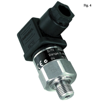
The switch/sensor shown in Fig. 4 is a typical transducer type model that offers this analogue reading of vacuum level in a system. These types of sensors do not offer a readout, so a dial gauge is often used as well.
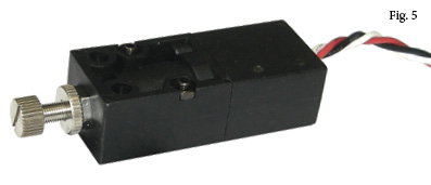
Other less expensive switches are available such as those shown in Fig. 5. This switch is a mechanical diaphragm type. As the vacuum level rises, a rubber diaphragm is drawn back, breaking or making the electrical circuit. These are very common due to the lower cost compared to the digital switches described earlier. The switching range is limited compared to digital models, offering a typical adjustment range between 10″Hg and 24″Hg. This is ideal for part presence indication in vacuum cup handling systems. The hysteresis (see below explanation) is fixed at about 3″Hg (10% vacuum).
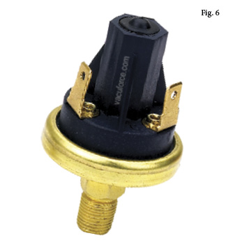
Other large-volume OEM-type switches such as the model shown in Fig. 6 are low cost offering a preset switching point and are found in mass-produced consumer products including automotive and domestic appliance products.
One of the challenges often associated with vacuum switches is the hysteresis value that is more often than not a fixed value on lower-priced models. Fig. 7 shows a switch that is purely mechanical but has an adjustable hysteresis feature included. Arrow “A” shows the vacuum range adjustment screw and arrow “B” shows the hysteresis adjustment screw. This type of switch is often used on a centralized vacuum pump system where the pump needs to turn on and off at specific vacuum levels.
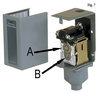
Hysteresis or switching differential is the difference between the switch position change value. A normally closed switch could be adjusted to open at 24″Hg (-80kPa). When the vacuum level falls (decreases) to 21″Hg, the switch changes back to its original state (contacts close). Therefore, this switch has a 3″Hg differential or hysteresis. This value, as with the switch in Fig. 7, is sometimes adjustable.
A vacuum system should contain all the correct components that are required to offer safe operation, long life of components, and reliability for the user. The system should also include, as explained in this overview article, instruments such as gauges and switches that offer the user known values for efficient production throughput and the fault finding tools that enable a quick prognosis for the maintenance engineer.
This article is intended as a general guide and as with any industrial application involving machinery choice, independent professional advice should be sought to ensure correct selection and installation.
Daniel Pascoe is President of Davasol Inc, an independent industrial consultant specializing in online brand presence and industrial e-commerce stores, with clients across North America and Europe, one of which is Vacuforce LLC (www.vacuforce.com) a manufacturer and distributor of vacuum components for whom this article was co-written with.
Daniel can be reached via www.davasol.com or directly at dpascoe@davasol.com. Find Vacuforce on twitter.com/vacuforce
Share this information.
Related Posts
Sensor Innovations Result in Proactive Maintenance
Pneumatic Cylinder Cushioning: Increasing the Efficiency of Your Entire Pneumatic System
Integrating the Hydraulic Filter Catridge on the Manifold: Can It Work?

Compact Hydraulics Is on the Move
Selecting the Best Sensors for Steering Systems
Safety Catchers
Sponsor

Sponsors