Vacuum Priming Systems
Walk into just about any private or government-run water pumping station where there is a need to pump water vertically from a lower level to a higher level, and seek out the most neglected and rust-covered piece of the equipment in the plant. You’ve just found a typical vacuum priming system as shown in Fig. 1. The rest of the equipment, including centrifugal pumps and a myriad of brightly colored valves, will gleam in comparison to this monster in the corner.
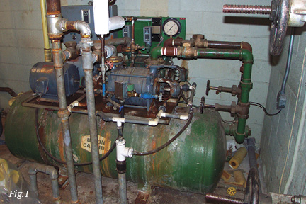
So what do we usually see when we look closely at one of these systems? They normally consist of one or two liquid ring vacuum pumps mounted on the top plate of a horizontal vacuum receiver tank, such as the one shown in Fig. 1. A simple control panel will be mounted on or close by this assembly, which offers a selector switch with basic on/off control buttons for pump “A” or “B.” As can be seen from Fig. 1, which has two liquid ring pumps side by side, there are pipes for feeding make-up water to the pumps. Usually the complete system has been leaking both sealing water and vacuum for years. Due to vacuum leaks, the system has usually been running almost continually, attempting to keep up with the required vacuum level set point. This is why it is severely corroded.
Fortunately, technology has moved on, and water pumping stations no longer have to rely on water-sealed vacuum pumps (liquid ring pumps) for this type of application. The disadvantages of water-sealed vacuum pump systems include high maintenance costs, as well as excessive use of motive energy. In addition, the vacuum level can fluctuate considerably as the seasons change and the sealing water temperature rises and falls, directly affecting the vacuum level. With this type of variable, it takes a very specialized maintenance team to set up these systems and keep them operating with peak performance.
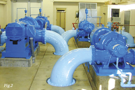
So with that all said, what does a vacuum priming system actually do? Those great big gleaming water impeller pumps (as shown in Fig. 2) are great for moving high volumes of water from one place to another, but—and this is the thing—they are unable to pump or move air. When the pump is running and pumping water at tremendous volume, everything is working as it should. However, when the pumps are taken offline and stop, the water drains from the pumps by gravity. Consequently, they need to be filled with water (or other liquids) before they can be started again. This is where the vacuum priming system is used to “pull” water into the water pump to allow it to start. Fig. 3 shows a basic circuit with a duplex vacuum priming pump station connected in this particular case to two water pumps.
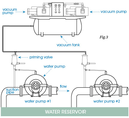
The vacuum priming system creates a vacuum from the highest point in the impeller pump, right down to the level of the water reservoir (lake, catch basin, ocean water inlet, etc.) that needs to be pumped. The vacuum pump system removes the air from the water pump suction line, as well as from inside the water pump chamber. As the air molecules are removed, the water from the reservoir is pushed up through the piping and replaces the void (lower pressure area) that this air previously occupied. A priming valve, which is mounted at the highest point on the water pump, is the connection point for the vacuum line that is running from the vacuum system to each of the water pumps. There are several types of priming valves, but the most common contains a float that automatically shuts off the vacuum suction line as soon as the water raises the float. This prevents water from reaching the vacuum pumps. Either a separate sensor or a connection from the priming valve indicates to the pump station operator that the pump is primed and therefore safe to start the water pump drive motor.
All of this sounds simple enough, but there are limitations to the height that a vacuum system can raise water, and that is usually regarded as a maximum of 10 meters. This distance is one of the principles of vacuum theory. The atmospheric pressure on our planet is 1,013 mbar (or 1 bar or 14.7 psi). For every 1 m of water depth, a pressure of 100 mbar is generated. Therefore, at a depth of 10 meters, the pressure is 1,000 mbar (or 1 bar or 14.7 psi). That’s a fact no matter where you are. At sea level, which is the lowest point on our planet, a full 1,000 mbar of atmospheric pressure is available. Therefore, a pump station at sea level can pull water up a distance of 10 meters (or 32.8 ft). If the pumps are higher than that, the water will not reach the pumps.
As a result, pumping stations in cities such as Denver, Co., a city known for being high above sea level, must be closer to the water source, as the atmospheric pressure is lower and less “vacuum” is available.
The vertical distance from the top of the water priming valve (and/or the vacuum pump) to the lowest level of the water to be raised must be known in order to select a vacuum pump with sufficient vacuum depth capabilities. This important factor should be taken into account when calculating the vacuum depth requirement in a pumping station that is required to raise water from a reservoir with fluctuating water levels or when pumping seawater from a tidal basin to a desalination plant.
When selecting a suitable vacuum priming system, it is necessary to consider not only the height that you wish to raise the water, but also the speed that you wish to accomplish the task. In an emergency, it is quite usual for several suction lines to be evacuated in quick succession. Therefore, not only is the maximum vacuum depth capability of your vacuum pump system important, but you must also calculate the speed of evacuation. This is normally determined by the pumping speed of the vacuum pumps selected for each individual system, and in North America, pumps are selected according to their cubic feet capacity per minute (cfm). Your vacuum pump specialist would need to advise you regarding this, as the capacity of evacuation reduces in direct proportion to the vacuum depth. Every vacuum pump is supplied with operating curves that will show you the pumping speed at various vacuum depths. For general purposes, to calculate the evacuation of a vessel (suction pipe and water pump) within a given amount of time, we use the following formula:
Time = T (minutes)
Pressure = P2 (in Torr)
Starting Pressure = P1 (In Torr)
Pump Capacity = C (cfm)
C = (V/T) In (P1/P2)
In this formula, vacuum is shown in Torr, which represents mm of mercury (mmHg). Torr is used because it is an absolute pressure scale in vacuum measurement.
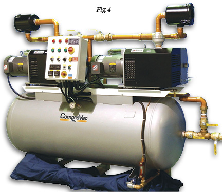
Today’s vacuum priming system looks nothing like the old rusting liquid ring systems of old. A modern vacuum priming system will still contain two vacuum pumps mounted on a vacuum receiver vessel, but this is where the similarity stops.
As shown in Fig. 4, the modern vacuum priming system typically uses an oil-lubricated rotary vane vacuum pump. This pump will have an operating vacuum level in excess of 29″Hg for evacuating water suction pipes to significant vertical depths. In addition, the capacity of the pump selection can be varied according to how fast you need to accomplish the task. The benefit of the oil-lubricated pump is the reduced motive power. Reduced motor hp = less energy costs. As sealing water is no longer required, leaks are a thing of the past. There is no water wastage and no more external rusting of the system. A modern electronic control panel complete with a graphical touch screen enables the operator to select the desired operating mode to suit his anticipated needs.
The system will automatically lead/lag or cascade the pumps on and off to offer equal operating hours, and minimum run timers will prevent the motors from overheating. Purge cycles will pump out vapor trapped in the system and prevent rusting of internal components and contamination of the lubricating oil. Visual and remote alarm systems are normally included within a basic system. A frequent option is an auto-drain system that will automatically evacuate any moisture that may find its way back to the vacuum receiver vessel, even when the system is in full operation. In the event of a catastrophic failure of one of the vacuum priming float valves, an electro-pneumatic valve will automatically isolate the vacuum circuit, preventing the vacuum priming system from flooding.
In today’s energy-conscious world and in industrial facilities where unplanned maintenance calls costs thousands of dollars an hour in lost production, key steps for ensuring a reliable and cost-effective solution include making sure the vacuum pump priming system does exactly what it should and understanding what the user expects.
Share this information.
Related Posts

2015 Systems Integrator Directory
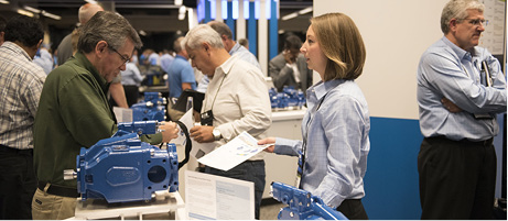
Eaton Brings Together Distributors, Customers, and End Users at Annual Distributor Meeting
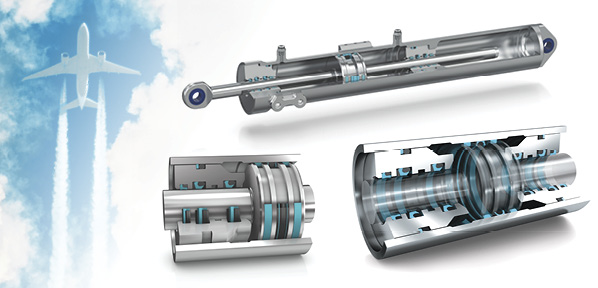
Hydraulic Sealing Solutions Help Jetliners Fly Higher, Faster, Longer

The Unvarnished Truth: Contamination Control Makes Servo Valves Click
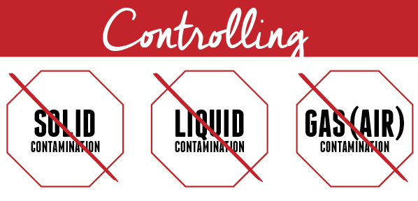
Controlling Contamination in Hydraulic Equipment
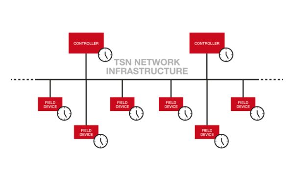
TSN Technology Boosts Digital Manufacturing
One thought on “Vacuum Priming Systems”
Leave a Reply
Sponsor

Sponsors
We need a pump fo r priming a centrifugal water pump taking suction from a 25 feet reservoir depth. What type of pump will be suitable?