Demystifying Pilot Ratios in the Overcenter/Counterbalance Valves
By Maurice A. J. Ashmore, Global Chief Engineer SICV & HIC, Eaton’s Hydraulics Business, Warwick UK
A common challenge in the design of hydraulically operated machines is selecting the right pilot ratio to use within the overcenter valve. In fact, many in the industry would say it’s the “be-all and end-all” factor when it comes to machine stability. That’s why many users demand for their replacement valve to have the same pilot ratio as its predecessor to avoid any surprises.
Despite its importance, there is a lot of mystery in the nuances surrounding the pilot ratio. In this article, we’ll try to clear up some of these details and provide some considerations for choosing an efficient solution in the overcenter value.
WHAT IS A PILOT RATIO?
An overcenter, or counterbalance, valve is a pilot assisted-relief valve with a free flow check. The pilot ratio refers to the ratio, or difference, between the pilot pressure area and the relief area as shown in Figure 1.
For the valve to open as a relief, pressure must be generated with resultant force that is sufficient to overcome the spring force. For most applications, the relief settings suggested are 30 percent above the maximum load induced pressure to ensure the machine can hold to its maximum capacity at all times – while also accounting for any system hysteresis.
During normal operation, pressure is typically applied to a separate port, normally taken from the other side of the actuator, where the area is larger than the relief seat area. This action causes the valve to open at a lower pressure.
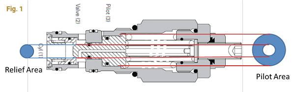
The pilot ratio is important in this scenario because it controls the range of pressure needed to take the valve from closed to fully open. It is also subject to variations in pilot pressure as the load changes due to mechanical advantage, machine unsteadiness or general unstable conditions. A lower pilot ratio requires a greater pilot pressure difference to fully open the valve, and any given load pressure change does not affect the valve as much as it does for a high pilot ratio (See Figure 2).
Instability can occur when the valve overreacts due to changes in load or mechanical friction within the machine. A low pilot ratio limits the movement of the poppet, therefore restricting the change in flow caused by the opening and closing of the valve.
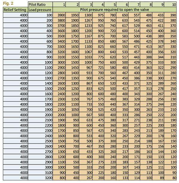
As the load pressure increases, the difference between the pilot pressure required for each ratio gets smaller – meaning a minor change in pilot ratio has little effect. For example: with a relief setting of 4,000psi and a load pressure of 2500psi for a 4:1 vs a 6:1 pilot ratio, the pilot pressure required to open the valve varies by only 125psi which is only 5 percent of the load pressure and 3 percent of the set pressure.
For each valve, different size pilot ratios are interchangeable so users can change the ratio by replacing the cartridge in the cavity of the manifold block or the cylinder in case of an unforeseen issue. Generally, the more unstable the load, the lower the pilot ratio should be to optimize machine stability.
Keeping Things Steady
At Eaton, we designed our overcenter valve solution to be intrinsically more stable in addressing challenges with pilot ratio by leveraging a direct-acting design. Using this approach, as opposed to a differential-area design, the main spring has a higher rate. The stiffness of the spring relates directly to the responsiveness of the valve to pressure fluctuations. For any change in load pressure, the valve will be less sensitive and not open as rapidly, reducing the rate of increase in the opening orifice and therefore the change in flow.
To help put this in context, imagine driving in your car with the suspension at a very soft setting. This action can cause the car to bounce at the slightest change in road conditions. Adjusting it to a stiffer setting of suspension, the car becomes more stable on the road with less rock and roll.
This is the principle Eaton uses to maintain stability with the overcenter valve while accommodating more efficient higher pilot ratios. The stiffness of the spring increases the pressure override when used as a relief valve. The relief function is designed to remove pressure spikes and as thermal relief – not so much as a full flow relief valve.
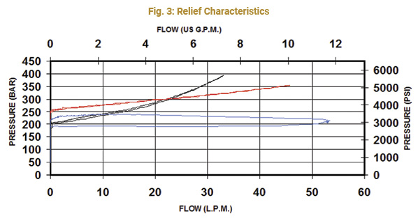
Figure 3 shows the relief performance of three different manufacturers’ overcenter product fittings in the same cavity. The blue line is a differential area design where small changes in pressure opens the valve quickly. This causes a more rapid opening of the valve when either the load pressure or the pilot pressure changes. Without significant hysteresis, this valve would always be unstable. The black line and the red line are direct acting designs where it takes a greater pressure difference to increase the flow, making them less likely to react to transient pressure changes.
In Summary
While there is a lot that goes into creating a stable machine, selecting the right pilot ratio for the overcenter valve remains a crucial consideration. To address more unstable loads, leveraging lower pilot ratios will provide better control. As the load pressure increases, changes in pilot ratio have very little effect on stability or performance.
While pilot ratios play an important role in ensuring stability, the design of the valve also affects the intrinsic stability of the product. Deploying an overcenter valve with steeper relief pressure override characteristics, as found in direct-acting design models, provides a more stable overall system. Bringing a higher rate of spring and more rigidity to the system, the platform can help users avoid the loss of machine control and ensure safety for personnel and property.
Share this information.
Related Posts
Drive-Through: Hydraulic AWD Takes It on the Road

Perfect Proportion: Closed Loop Control for Mobile Applications
Specifying Pneumatic Cylinders – Part 2
4 Common Misconceptions About Cobots
Hydraulic Hose Assembly Application Guidelines – ISO/TS 17165-2
Preventative Maintenance of Pressure Regulators
Sponsor

Sponsors